background image

14

BA-en-3018-2006_KNH18

3.5 Connecting the high voltage cable to the generator and to the 

distribution box

Warning!

Electric shock hazard!
Work may be carried out only if:
• the supply voltage to the generator has been disconnected,
• the machine is at a standstill because the bars pick up charges if the 

material web is running.

Method:

Connect the bars via the prefabricated high voltage cable. Push the high 
voltage cables up to the stop into the socket connection. Finally, secure 
the adapter inside the socket with the clip provided.
Cables without adapters have a color-coded marking on the flexible 
tubing. This marking must lie flush with the outside edge of the coupling.

Note:

 The clip must be fully inserted.

correct       

                    incorrect

Caution!

The high voltage cable must be pushed up to the stop (90 mm) into the 
cable inlet! The connecting area of the high voltage cable must be kept 
clean!

Fig. 4:
Connecting the 
high voltage cable

Z0

01

78y

Fig. 5:
Inserting the clip

Z0

00

18y

Summary of Contents for KNH18

Page 1: ...Operating Instructions KNH18 High Voltage Generator BA en 3018 2006 F00021 ...

Page 2: ...2 BA en 3018 2006_KNH18 ...

Page 3: ...es 12 3 4 Charging bars suitable for connection 13 3 5 Connecting the high voltage cable to the generator and to the distribution box 14 3 6 Disconnecting the high voltage cable 15 3 7 Connecting the supply voltage 15 3 8 Connecting the release signal 16 4 Operation 17 4 1 Start up 17 4 2 Use 17 5 Maintenance 18 5 1 High voltage generator 18 5 2 Charging bars 18 6 Warranty 19 7 Troubleshooting 19 ...

Page 4: ...4 BA en 3018 2006_KNH18 ...

Page 5: ...to Operating Instructions R120 R121A and R23ATR The output voltage of the KNH18 high voltage generator is selected via the rotary button in the front panel High voltage is released via an external 24 V signal Please read these instructions carefully before starting the unit This will help you prevent personal injuries and damage to property Simply give us a call if you have any suggestions proposa...

Page 6: ... output 2 3 Ground terminal 4 Connector release signal not with type KNH18 __D 5 Socket system input 6 Fuse see nameplate 7 Master switch ON OFF 8 Rotary button for setpoint settings not with type KNH18 __D 9 Pilot lamp Fig 1 KNH18 High Voltage Generator Z00093y KNH18 1 2 3 4 5 6 7 8 9 ...

Page 7: ...efers to operations which if carried out improperly may result in damage to property Ex Warning For units with EX approval only This symbol denotes the special conditions which must be observed when operating the system in explosion hazard areas as specified in the EX approvals 2 2 Contact protection The site of installation and or use of the units is outside the control of Eltex contact protectio...

Page 8: ...ter malfunctions switch off the high voltage genera tor and disconnect the mains power supply see chapter 5 Mainte nance page 18 chapter 7 Troubleshooting page 19 Any work involving the units must be carried out by qualified electri cians see chapter 5 Maintenance page 18 chapter 7 Troubleshoot ing page 19 Before carrying out any work involving the units the machine which has the units fitted must...

Page 9: ...tion page 17 Select the desired output voltage via the rotary button High voltage may also be present if the rotary button is turned fully anti clockwise to the stop see chapter 4 2 Use page 17 The generator must be checked regularly to ensure its proper function ing The connections of the high voltage cables must be free of dirt and other foreign matter see chapter 5 1 High voltage generator page...

Page 10: ...xceeded e g in Germany the ozone concentration occurring during the operation of the system must not exceed the recommended value based on interna tional limits of 0 06 ml m 0 12 mg m Static on personnel Static charges on personnel are unlikely if the bars are installed prop erly Personnel must wear conductive footwear Please note all national regulations regarding electrostatic charge e g TRGS 72...

Page 11: ...of the unit is not impaired The site of installation must be dry and free of dust if possible Air circula tion above the cooling ribs must not be obstructed 3 2 Grounding Before putting the high voltage generator into operation make sure that the appliance is permantly grounded via the ground terminal 3 Fig 1 The ground cable should have a minimum cross section of 1 5 mm2 and be connected to groun...

Page 12: ...ield the low voltage cable If the high voltage cables are led through bores in conductive grounded materials the minimum bore diameter D is calculated as follows from the wall thickness of the material D 60 mm wall thickness Allow the biggest possible radius for the edges of the bore hole Use an insulating grommet to centre the cable If ungrounded and conductive objects are placed near 2m the high...

Page 13: ...ctions R120 R121A The KNHV3 distributor box available as an optional extra allows the user to increase the number of bars connected When using this option make sure that the sum of the bar currents does not exceed 1 3 mA Example current per meter of active bar length 1 mA Sum of active bar lengths 1 3 m maximum total current 1 3 mA Fig 3 Installing the generator the distributor box and the chargin...

Page 14: ...tage cable Push the high voltage cables up to the stop into the socket connection Finally secure the adapter inside the socket with the clip provided Cables without adapters have a color coded marking on the flexible tubing This marking must lie flush with the outside edge of the coupling Note The clip must be fully inserted correct incorrect Caution The high voltage cable must be pushed up to the...

Page 15: ... Then pull out the cable A conversion kit comprising terminal adapter tubular rivet split pin plug and washer is available as accessory from Eltex 3 7 Connecting the supply voltage Supply voltage connection to the high voltage generator is made directly via the mains plug using the enclosed mains cable Warning Disconnect and or connect the mains cable on the socket only when off load When using ex...

Page 16: ...ries Note We recommend enabling disabling the 24 V release signal via a machine contact so that the high voltage is disabled when the machine is not run ning This configuration will ensure that high voltage is not applied at the bars with the machine stopped Fig 6 Pin assignment for the 24 V release signal PIN 1 24 V DC PIN 2 PIN 3 PIN 4 PIN 5 0 V Z00185y 1 2 3 4 5 Fig 7 Connecting cable KS C for ...

Page 17: ...ly after the supply voltage is switched on High voltage applies at the outlet sockets as soon as the 24 V release signal is transmitted The pilot lamp ligths up when the high voltage is switched on 4 2 Use Select the desired output voltage via the rotary button Warning High voltage may also be present if the rotary button is turned fully anti clockwise to the stop Anti clockwise turn Reducing the ...

Page 18: ...must be free of dirt and other foreign matter The intervals for the check depend on the application and must hence be defined by the user according to the operating conditions The generator itself does not require any maintenance 5 2 Charging bars To ensure the proper function of the charging bars clean weekly with compressed air free of oil and water max 6 bar and a brush with soft plastic bristl...

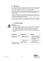
Page 19: ...e If repairs are required at the customer s premises the costs for sending a technician travel travel time expenses will be charged to the customer 7 Troubleshooting Warning Electric shock hazard Do not carry out any maintenance or repair work without first switching off the high voltage generator and disconnecting the supply voltage The machine which has the units fitted must not be in operation ...

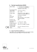
Page 20: ...y rotary button AC component of the output voltage 25 at Umax and Imax Output current max 1 3 mA Supply voltage 230 VAC 10 50 Hz KNH18_2_ 115 VAC 10 60 Hz KNH18_1_ Fuse Fuse type see nameplate Power input max 75 VA Enclosure Sheet metal steel 1 5 mm painted aluminium anodised Protection class IP40 Operating ambient temperature 0 60 C 32 140 F Storage temperature 20 70 C 4 158 F Ambient humidity ma...

Page 21: ...BA en 3018 2006_KNH18 21 9 Dimensions Fig 8 Dimensions KNH18 high voltage generator Z00181y 330 100 212 128 170 M8 M8 M6 M6 386 2 5 410 27 ...

Page 22: ... tube for 30 kV charging bars 104165 Hexagonal crimper 5 41 mm 102952 High voltage distributor box for max 4 components KNHV3 Fuse clip mains power cable ELM00545 Generator supporting plate MCH08667 Bolts for generator supporting plate MSR00209 Mains power cable Standard specify cable length KN AA___ Mains cable without plug open on consumer side specify cable length KN AD___ Signal cable for 24 V...

Page 23: ......

Page 24: ... mbH Blauenstraße 67 69 79576 Weil am Rhein Germany Phone 49 0 7621 7905 422 eMail info eltex de Internet www eltex de Eltex offices and agencies The addresses of all Eltex agencies can be found on our website at www eltex de Z01007y ...

Reviews: