background image

© Elsys AG 

Page 4 


Specifications 

Channel specifications: 

Input sensitivity 

:  See table below 

Input impedance Diff on 

:  approx. 102k

 || 10pF 

Input impedance Diff off 

:  approx. 17k


Bandwidth 

:  30 Hz to 30kHz 

Max. input voltage 

±

 35V (short peaks up to 250V) 

Pulse output 

:  TTL (0.4 ... 3.5 V), Pulse width 5

µ

s, Impedance 100


All other outputs 

:  Impedance 560


Specifications of the Base Unit: 

Number of channels 

:  One per Plug-In Module (up to 14 in one chassis) 

Supply voltage 

:  95 .. 230 VAC, fused with two fuses 1AT 

Dim. of Rack Chassis 

:  19”, 480 x 134 x 260 mm   (W x H x D) 

Weight 

:  Rack chassis with 14 channels: 5.3 kg 

one plug-In channel: approx. 0.23 kg 


Input sensitivity and trigger level with Differentiator switched OFF  

(for Reluctance Sensors): 

  Signal: Sinus, symmetric to zero line, Frequency 30Hz ... 30kHz 

  Gain factor: See table below 

  Polarity: May be neglected 


Differentiator: Off 

  Time constant from Differentiator: May be neglected 


Gain 

Responsivity, approx. 

100 mVpp 

10 

10 mVpp 

100 

1 mVpp 

Auto 

2 mVpp 


Input sensitivity and trigger level with Differentiator switched ON  

(for Capacitive and Eddy-current Sensors):


  Signal: Sinus, symmetric to zero line 

  Gain factor: See table below 

  Polarity: May be neglected 


Differentiator: On 

  Time constant of Differentiator: See table below 


Responsivity, approx. 


Frequency 

dU/dt 

Gain 1 

10 

100 

Auto 

20 Hz 

Flat 

5 Vpp 

0.5 Vpp 

1 Vpp 

100 Hz 

Flat 

12 Vpp 

1.2 Vpp 

0.12 Vpp 

0.25 Vpp 

1 kHz 

Flat 

1.2 Vpp 

0.2 Vpp 

0.012 Vpp 

0.025 Vpp 

1 kHz 

Steep 

2.5 Vpp 

0.25 Vpp 

0.5 Vpp 

10 kHz 

Steep 

2.5 Vpp 

0.25 Vpp 

0.025 Vpp 

0.05 Vpp 

40 kHz 

Steep 

1.5 Vpp 

0.15 Vpp 

0.015 Vpp 

0.025 Vpp 


31.10.2007, Elsys AG, CH-5443 Niederrohrdorf 
Description-EL-TRIG_R_Rack.doc


Summary of Contents for EL-BU-14/TRIG_R

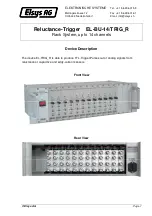
Page 1: ...escription The device EL TRIG_R is able to produce TTL Trigger Pulses out of analog signals from reluctance or capacitive and eddy current sensors Front View Rear View ELEKTRONISCHE SYSTEME Tel 41 56 496 01 55 Mellingerstrasse 12 Fax 41 56 496 01 61 CH 5443 Niederrohrdorf Email info elsys ch ...

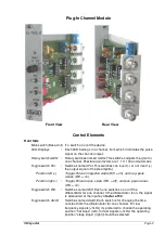
Page 2: ...signal of the preamplifier Position left Trigger Pulse on negative slope Diff off and neg peak values Diff on Position right Trigger Pulse on pos slope Diff off and pos peak values Diff on Toggle switch Diff Switches named Diff Each one switches on or off the differentiator for one channel If the differentiator is on the signal is attenuated at the input by a factor of 50 Toggle switch dU dt Switc...

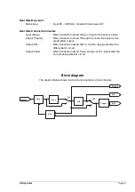
Page 3: ...to monitor the signal at the preamplifier output Output Diff BNC Connector named Diff to monitor the signals after the differentiator circuit Output Pulse BNC Connector named Pulse Output of TTL signal after the zero crossing detector circuit Block diagram The graphic below shows the functional operation of one channel A m p I n v e r t D i f f T r i g g e r S e n s o r P u l s P o l D i f f o n o...

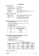
Page 4: ...Signal Sinus symmetric to zero line Frequency 30Hz 30kHz Gain factor See table below Polarity May be neglected Differentiator Off Time constant from Differentiator May be neglected Gain Responsivity approx 1 100 mVpp 10 10 mVpp 100 1 mVpp Auto 2 mVpp Input sensitivity and trigger level with Differentiator switched ON for Capacitive and Eddy current Sensors Signal Sinus symmetric to zero line Gain ...

Reviews: