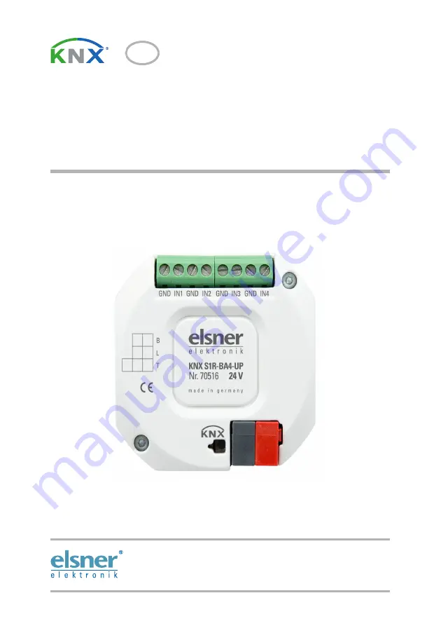
KNX S1R-BA4-UP 24 V
Actuator for a 12-24 V DC motor
Item number 70516
EN
Installation and Adjustment
Page 1: ...KNX S1R BA4 UP 24 V Actuator for a 12 24 V DC motor Item number 70516 EN Installation and Adjustment ...
Page 2: ......
Page 3: ...st of all communication objects 10 6 Parameter setting 20 6 1 General settings 20 6 2 Output 20 6 2 1 Channel settings drives 21 6 2 1 1 Control drives 23 6 2 1 2 Manual 30 6 2 1 3 Automation external 31 6 2 1 4 Automatic internal for shading drives 31 6 2 1 5 Automatic for windows drives 36 6 2 1 6 Scenes drives 40 6 2 1 7 Button inputs drives 40 6 2 2 Output channel with drive 46 6 2 3 Connectio...
Page 4: ...leshooting of the device must only be carried out by a competent electrician Safety advice Safety advice for working on electrical connections components etc DANGER indicates an immediately hazardous situation which will lead to death or severe injuries if it is not avoided WARNING indicates a potentially hazardous situation which may lead to death or severe injuries if it is not avoided CAUTION i...
Page 5: ...of the drives for positioning incl fault reporting object Position feedback movement position also slat position for shutters Position storage movement position via 1 bit object storage and call up e g via buttons Parameters for taking drive and mechanics downtimes into account Control via internal or external automation functions Integrated shade control with slat tracking according to sun positi...
Page 6: ...t 12 24 V DC typically 5 mA max 10 mA Maximum load Each terminal contact may be loaded with a maximum of 10 A Output 1 Output potential free with polarity changer for 1 drive or 2 electrical loads Connections Motor 1 Motor 2 Power supply 12 24 V DC for connected Motor consumer required via connections Load capacity max 5 A with resistive load Starting current max 5 A Minimum current for runt ime m...
Page 7: ...teed The device is only to be used for the intended purpose described in this manual Any improper modification or failure to follow the operating instructions voids any and all warranty and guarantee claims After unpacking the device check it immediately for possible mechanical damage If it has been damaged in transport inform the supplier immediately The device may only be used as a fixed site in...
Page 8: ...uld be moved to a save position if there are anticipated weather conditions for example if this has not already been done by the automatic function product protection If the power supply is removed the connected drive switches off When the power is restored the consumer remains switched off until a new movement command is re ceived by the actuator 2 3 Installation Fig 1 Bus side 1 Connector analog...
Page 9: ...the guidelines and standards for SELV electric circuits while installing and cable laying of the KNX connection and inputs ATTENTION When first switched on relays may be live The bistable relays used in this product can switch themselves on when subjected to strong vibration e g during transport First of all connect the bus voltage this will switch off the relays Only then can the power supply for...
Page 10: ...nd errors excepted 2 4 1 Connection examples Inputs Drive 12 to 24 V DC at the out put 2 consumers 12 to 24 V DC at the out put Each terminal contact may be loaded with a maximum of 10 A Fig 3 Example KNX S1R B4 UP with binary contact on input 1 and T NTC temperature sensor on input 4 Connection of the temperature sensor is in dependent of the polarity ...
Page 11: ...ase no information can be received or sent via the bus For KNX devices with safety functions e g wind or rain blocks it is important to set up periodical monitoring of the safety objects The ideal ratio is 1 3 example if the weather station sends a value every 5 minutes the actuator must be configured for a monitoring period of 15 minutes 3 Addressing of the device at the bus The device is supplie...
Page 12: ...ing 1 Byte 104 Channel A Manual slat position Input RWC 5 1 DPT_Scaling 1 Byte 105 Channel A Automatic extended Input RWC 1 8 DPT_UpDown 1 Bit 106 Channel A Automatic brief Input RWC 1 8 DPT_UpDown 1 Bit 107 Channel A Automatic movement position Input RWC 5 1 DPT_Scaling 1 Byte 108 Channel A Automatic slat position Input RWC 5 1 DPT_Scaling 1 Byte 109 Channel A Switch from manual to automatic Inpu...
Page 13: ...h 1 Bit 126 Channel A Outdoor temperature blocking measurement value Input RWC 9 1 DPT_Value_Temp 2 Bytes 127 Channel A Outdoor temperature blocking status Output R CT 1 1 DPT_Switch 1 Bit 128 Channel A Twilight object Input RWC 1 1 DPT_Switch 1 Bit 129 Channel A Twilight measurement value Input RWC 9 4 DPT_Value_Lux 2 Bytes 130 Channel A Twilight status Output R CT 1 1 DPT_Switch 1 Bit 131 Channe...
Page 14: ...ch 1 Bit 145 Channel A Shading position learning object Input RWC 1 1 xxx 1 Bit 146 Channel A Azimuth Input RWC 9 9 xxx 2 Bytes 147 Channel A Elevation Input RWC 9 9 xxx 2 Bytes 148 Channel A Cold air intake blocking object Input RWC 1 1 DPT_Switch 1 Bit 149 Channel A Cold air intake outside temp measurement value Input RWC 9 1 DPT_Value_Temp 2 Bytes 150 Channel A Cold air intake blocking status O...
Page 15: ...ning object Output R CT 1 1 DPT_Switch 1 Bit 165 Channel A Inside humidity opening object Input RWC 1 1 DPT_Switch 1 Bit 166 Channel A Inside humidity opening measurement value Input RWC 9 7 DPT_Value_Humidity 2 Bytes 167 Channel A Inside humidity opening status Output R CT 1 1 DPT_Switch 1 Bit 170 Channel A Zero position reached Input RWC 1 1 DPT_Switch 1 Bit 171 Channel A Zero position sensor di...
Page 16: ...nt value Input RWC 9 5 DPT_Value_Wsp 2 Bytes 188 Channel A Blocking 2 Wind blocking status Output R CT 1 1 DPT_Switch 1 Bit 189 Channel A Blocking 2 Rain blocking object Input RWC 1 1 DPT_Switch 1 Bit 190 Channel A Blocking 3 Blocking object Input RWC 1 1 DPT_Switch 1 Bit 191 Channel A Blocking 3 Wind blocking object Input RWC 1 1 DPT_Switch 1 Bit 192 Channel A Blocking 3 Wind blocking measurement...
Page 17: ...ocking object Input RWC 1 1 DPT_Switch 1 Bit 207 Channel A Short time restriction Input RWC 1 1 DPT_Switch 1 Bit 210 Channel A1 Switching Input RWC 1 1 DPT_Switch 1 Bit 211 Channel A1 Feedback Output R CT 1 1 DPT_Switch 1 Bit 212 Channel1 A1 Status Readable R C 1 1 DPT_Switch 1 Bit 213 Channel A1 Blocking object Input RWC 1 1 DPT_Switch 1 Bit 215 Channel A1 Start staircase light function Input WC ...
Page 18: ...5 Input 1 Temperature encoder Output R CT 9 1 DPT_Value_Temp 2 Bytes 256 Input 1 Brightness encoder Output R CT 9 4 DPT_Value_Lux 2 Bytes 257 Input 1 Scene Output R CT 18 1 DPT_SceneControl 1 Byte 258 Input 1 Blocking object Input RWC 1 1 DPT_Switch 1 Bit 260 Input 1 Temperature sensor malfunction Output CT 1 1 DPT_Switch 1 Bit 261 Input 1 Temperature sensor total value Output R CT 9 1 DPT_Value_T...
Page 19: ...0 Input 3 Temperature sensor malfunction Output CT 1 1 DPT_Switch 1 Bit 301 Input 3 Temperature sensor total value Output R CT 9 1 DPT_Value_Temp 2 Bytes 302 Input 3 Temperature sensor measured outside value Input WC 9 1 DPT_Value_Temp 2 Bytes 303 Input 3 Temperature sensor measured value Output R CT 9 1 DPT_Value_Temp 2 Bytes 320 Input 4 Temperature sensor malfunction Output CT 1 1 DPT_Switch 1 B...
Page 20: ...bit encoder Output R CT 5 5 xxx 1 Byte 475 Input 4 Temperature encoder Output R CT 9 1 DPT_Value_Temp 2 Bytes 476 Input 4 Brightness encoder Output R CT 9 4 DPT_Value_Lux 2 Bytes 477 Input 4 Scene Output R CT 18 1 DPT_SceneControl 1 Byte 478 Input 4 Blocking object Input RWC 1 1 DPT_Switch 1 Bit 500 Temp threshold value 1 Measured value Input WC 9 1 DPT_Value_Temp 2 Bytes 501 Temp threshold value ...
Page 21: ...1 DPT_Value_Temp 2 Bytes 516 Temp threshold value 3 1 0 Input WC 1 1 DPT_Switch 1 Bit 517 Temp threshold value 3 Switching delay from 0 to 1 Input WC 7 7 xxx 2 Bytes 518 Temp threshold value 3 Switching delay from 1 to 0 Input WC 7 7 xxx 2 Bytes 531 9 Temp threshold value 3 Switching output Output R CT 1 1 DPT_Switch 1 Bit 520 Temp threshold value 3 Switching output block Input WC 1 1 DPT_Switch 1...
Page 22: ...es page 23 Automatic functions Automatic can be specified externally or internally see Movement limits page 30 or Automatic for windows drives page 36 Scenes Movement positions see Scenes drives page 40 Button inputs Configuration as actuator button bust button or for zero position sensor see Button inputs drives page 40 Settings for switch functions Channels are divided into two switches A1 A2 Ge...
Page 23: ...ator specifies the end positions with help from the greater current on the drive output For this regular reference movements see below should be set If a dead time is observed while starting the curtain then this can be entered manually at this point or calculated automatically Obey the manufacturer s instructions for the curtain Exchange UP DOWN shutter blinds Exchange ON OFF awning Exchange OPEN...
Page 24: ...ge of direction of the drive should be adjusted according to the specifications of the motor manufacturer Reference movement With the regular movement to the two end positions the runtime and zero position are adjusted again This is especially important for the automatic runtime determination Therefore it can be set here after how many movements before a positioning movement a reference movement w...
Page 25: ...of two drive mechanisms is prioritised and is parameterised as master and the other one as slave By means of zero position sensors both actuators know the own current status and the current status of the other one This one is either in a safe position or not in a safe position The safe position is reached as soon as the drive mechanism is in a sector where a collision is not possible for an awning...
Page 26: ...r command to the awning This is the signal for the awning to retract a little bit As soon as the awning has reached a safe position there is an according feedback signal of the zero position sensor of the awning Only now the window opens Master and slave regularly exchange their positions safe or not safe By means of the monitoring period you may adjust the frequency of information retrieval The s...
Page 27: ...s correspond to the sequence listed Block 1 has the highest priority Block 5 the lowest Actuator is master Send repetition for master command in sec 1 255 10 Monitoring period for slave status and zero position object in sec 1 255 10 Actuator is slave Send repetition for slave commands in sec 1 255 10 Monitoring period for master status and zero position object in sec 1 255 10 Movement position fo...
Page 28: ...atic is reactivated Use Block 5 low priority no yes with blocking object yes as wind blocking yes as rain blocking Priority is Block 5 over Manual Manual over Block 5 Use monitoring of blocking objects No Yes Monitoring period for blocking objects only if using monitoring of the blocking objects 5s 2 h 5 min Behaviour if a blocking object is not received only if blocking object monitoring is used ...
Page 29: ...l Here it is specified was happens for object value 1 and 0 Via the free blocking object a fire alarm scenario may be configured for example create escape routes by retracting the shading smoke extraction via windows This can prevent being locked out on the patio opened window contact of the patio door blocks the shutter in front of the door Use automatic blocking object no yes Operating mode afte...
Page 30: ...e the 1st communication and bus voltage return 0 1 Designation Wind blocking Enter a designation here Type of input object 1 bit 16 bit Type of input object 1 bit If blocking object has value 1 no action stop move into position up command down command shutter blind retract command extend command awning close command open command window Position in only if by using a block a specific position is ac...
Page 31: ...re and after blocking no action move into last position For automatic operation after blocking follow automatic Send current blocking status no yes Designation rain blocking Enter a designation here If blocking object has value 1 no action stop move into position up command down command shutter blind retract command extend command awning close command open command window Position in only if by usi...
Page 32: ...ement and the slat position can be stored Limitation type full movement position slat angle for shutters allow UP only allow DOWN only Value of the object in front of 1 Communication and bus voltage restoration 0 1 Limitation type movement position Movement allowed in the position range from in 0 100 to in 0 100 Limitation type slat angle Movement allowed in the angle range from in 0 100 to in 0 1...
Page 33: ...s twilight outdoor and indoor temperature time and position of the sun must be present in the bus system Outdoor temperature block The input object outdoor temperature block is linked with the output object of a temperature sensor The input object can be a 1bit object smaller or larger than a threshold value as well as a 16bit object measurement value 1 bit input object Shading is allowed if the b...
Page 34: ...orted from the 16bit object and evaluated Shading is allowed if the measurement value is greater than or equal to the target value difference Use twilight time control no only twilight control only time control both OR linking Use twilight time control only twilight control both Type of twilight object 1 bit 16 bit Type of twilight object 16 bit Twilight threshold value in lux 1 1000 10 Switching ...
Page 35: ... parameter or communication object For several brightness measurement values 2 x 16 bit or 3 x 16 bit only the maximum brightness value is compared to the threshold value Threshold value per parameter Set the threshold value and delay times for shading prevents constant opening and closing when light conditions change quickly Threshold value per communication object The threshold value is received...
Page 36: ...amming Start threshold value in klux valid until 1st communication 0 100 30 Type of limit value change Absolute value with a 16bit comm object Lifting lowering with a comm object Lifting lowering with two comm objects Increments in klux only when lifting lowering with comm object 1 5 2 Drive up delay in min 0 255 12 Drive down delay in min 0 30 1 Send current shading status no yes Assess position ...
Page 37: ... elevation ranges can be set A fixed curtain and slat position is specified for each Position of the sun is defined via directions regarding azimuth and elevation Directions East azimuth 0 180 South east azimuth 45 225 South azimuth 90 270 South west azimuth 135 315 West azimuth 180 360 Should the slats follow the elevation no yes Should the slats follow the elevation no Slat position in 0 100 75 ...
Page 38: ... In order to fully utilize the internal ventilation automatic information about the outdoor and indoor temperature and the inside air humidity must be present in the bus system Cold supply air lock The input object cold supply air block is linked with the output object of a temperature sensor The input object can be a 1bit object smaller or larger than a threshold value as well as a 16bit object m...
Page 39: ...ocked if the outdoor measurement value is greater than or equal to the indoor measurement value difference 16bit input object target actual temperature For this function the target value and actual value measurement values are imported from the 16bit object and evaluated Ventilation is allowed if the outdoor measurement value is smaller than the target value difference hysteresis and blocked if th...
Page 40: ... is received via the communication object and can be changed additionally e g button for target temperature and Open window never if too high temperature if too high room air humidity if too high temperature or room air humidity Type of temperature input object 1 bit 16 bit 16 bit target actual temperature Type of temperature input object 1 bit Type of temperature input object 16 bit Indoor temper...
Page 41: ...ct then enter the opening position in If the ventilation is controlled by temperature and humidity via a 16bit input object then you can either set an opening position or open the windows incrementally In the Type of limit value change Absolute value with a 16bit comm object Lifting lowering with a comm object Lifting lowering with two comm objects Increments only when lifting lowering with comm o...
Page 42: ...el Every drive can have up to 16 scene save points for movement positions Activate a scene save point Assign a scene number to the scene save point Use this scene number to call save the movement position stored in the actuator Make sure that every scene number is used only once per drive channel Set the movement position If it is allowed to save scenes via the bus this position only applies after...
Page 43: ...eded bus functions Thus the inputs can easily be configured as a switch drive control dimmer for sending values and for the scene calls Input as switch If a button with switch function is assigned to the input select the bus function Switch and specify which value is sent when pressing releasing the button and when it will be sent Operating mode Use input 1 no as a bus button as an actuator switch...
Page 44: ...indow control If the input to the drive control is used via the bus select the bus function shutter awning blinds or window and specify the button function and control mode Send value no change for change to 1 for change to 0 for change and cyclical for change to 1 and cyclical for change to 0 and cyclical Cycle if sent cyclical 5 s 10 s 30 s 1 min 2 min 5 min 10 min 20 min 30 min 1 h 2 h Use bloc...
Page 45: ... using a blocking object For active blocking there is no bus communication Input 8 bit encoder If the input is to be used as an 8bit encoder select the 8 bit encoder bus function and specify which value will be sent Button function Up Down Up Down Up Down On Off On Off Open Closed Open Closed shutter blinds awning window Control mode Standard Standard inverted Comfort mode Dead man s switch Use bl...
Page 46: ...ightness encoder e g threshold value of a sun sensor select brightness encoder and specify which value will be sent The input can be blocked using a blocking object For active blocking there is no bus communication Input for scene control If scenes are called and saved with the input then choose the Scenes bus function and specify the saving time difference call save and scene number The input can...
Page 47: ...e button function and the control mode A detailed description of the setting options for the individual control modi can be found in the chapter Control modi for drive control page 47 The input can be blocked using a blocking object No operation is possible for an active block Bus function Temperature sensor NTC Use malfunction object No Yes Offset in 0 1 C 50 50 0 Use external measured value No Y...
Page 48: ...ove incrementally or stops If operated longer the drive will move up to the end position The time difference between short and long is set individually Standard inverted When pushed shortly the drive moves up to the end position When pushed for longer the drive moves incrementally or stops The time difference between short and long and the repeat interval is set individually Send malfunction messa...
Page 49: ...ch The drive moves as soon as the button is actuated and stops as soon as the button is released Point in time 0 Actuate of button start of time 1 Release before time 1 expired step or stop if drive is moving Point in time 1 End of time 1 start of time 2 Moving command Release after time 1 expired but before time 2 expires Stop Release after time 1 2 expired Move into end position Control mode Com...
Page 50: ... object numbers refer to the mutual master slave coupling of drives at the output channel A and channel B Actuator A is Master zero position sensor at input 1 of the actuator Actuator B is Slave zero position sensor at input 1 of the actuator IN 1 IN 1 zero position zero position Master Drive 1 at channel A Slave Drive 2 at channel B Master command Master zero position status Slave zero position s...
Page 51: ...r at input 1 of the actuator IN 1 zero position zero position Master Drive 1 at channel A Slave Drive 2 at channel B Master command Master zero position status Slave zero position status 173 172 176 175 174 177 Zero position reached 170 of drive 1 of drive 2 sensor sensor IN 1 zero position zero position of drive 1 of drive 2 Master Drive 1 at channel A Slave Drive 2 at channel B Master command Ma...
Page 52: ...t linking and that is turned on during a fire alarm blocking zero position zero position of drive 1 of drive 2 Master Drive 1 at channel A Slave Drive 2 at channel B Master command Master zero position status Slave zero position status 173 172 176 175 174 177 Zero position reached 170 170 sensor sensor 210 Channel A1 Switching with stair 215 Channel A1 Switching Input Staircase light funct Start c...
Page 53: ...ge 50 6 2 5 1 Connection switch functions The menu item connection appears only for the settings for the switch function channel if selected Use switch functions Yes In the connection object Channel X connection different communication objects can be linked with AND or OR E g a light can only be switched on if the button input is active AND twilight is active Relay operation closer opener Behavior...
Page 54: ...essing the button again and what happens when a switch off telegram arrives from the bus Switch off delay The switch off delay is set with a time basis and time factor e g 1 min 4 corresponds to 4 minutes Additionally it is specified if the time interval for a repeat receipt of a switch off telegram is extended can be triggered again e g by pressing the button again and what happens when a switch ...
Page 55: ...used as actuator button or bus button If a temperature sensor eg T NTC is connected the input is configured as a push button with function temperature sensor NTC Input as bus button See Output page 20 Input as actuator button If the input to the control of the device is used at this channel then specify the button function If a button with switch function is assigned to the input select the button...
Page 56: ...e The Actuator KNX S1R BA4 UP 24 V provide four threshold values for temperature 6 3 1 Temperature threshold value 1 2 3 4 Threshold value Set the threshold values directly in the application program using parameters or define them via the bus using a communications object Command when pressing the button switch on switch off nothing Command when releasing the button switch on switch off nothing U...
Page 57: ... The current value is saved in EEPROM so that this is retained in the event of a power supply failure and will be available once the power supply is restored Switching output Set the behaviour of the switching output when a threshold value is exceeded undercut The output switching delay can be set using objects or directly as a parameter Threshold value setpoint using Parameter Communications obje...
Page 58: ...et using objects None 1 s 2 s 5 s 10 s 2 h Switching output sends on change on change to 1 on change to 0 on change and periodically on change to 1 and periodically on change to 0 and periodically Send cycle is only sent if periodically is selected 5 s 10 s 30 s 2 h Use switching output block No Yes Analysis of the blocking object At value 1 block At value 0 release At value 0 block At value 1 rel...
Page 59: ...R BA4 UP 24 V Version 27 05 2020 Technical changes and errors excepted Switching output sends on change to 1 and periodically If switching output 1 send 1 Switching output sends on change to 0 and periodically If switching output 0 send 0 ...
Page 60: ...mbH Control and Automation Engineering Sohlengrund 16 75395 Ostelsheim Phone 49 0 70 33 30 945 0 info elsner elektronik de Germany Fax 49 0 70 33 30 945 20 www elsner elektronik de Technical support 49 0 70 33 30 945 250 ...