background image

26

Parameter setting

Sensor Sewi KNX L-Pr

 • Version: 26.10.2021 • Technical Changes and Errors excepted.

However, in the meantime a second person has entered the corridor who is detected
by a slave. This person would be in darkness and would have to wait for the slave's
next transmission cycle before the light would be switched on again.

To prevent this, the switch command is connected to the "master: central off" object.
As a result, the master sends a cycle reset command to the slave if the light is switched
off manually. In the present example, the master would immediately switch the light
back on. 

8.4.

Light control

For light control, the sensor detects the brightness in the room. Activate the light con-
trol. 

Set, in which cases the 

data

received via object for setpoint value, setpoint value-ac-

tual difference, dimming increment and times are to be retained. Please note that the
setting "After power supply restoration and programming" should not be used for the
initial start-up, as the factory settings are always used until the first communication.

Set the 

setpoint value for the brightness in the room 

and specify whether, besi-

des the dimming information defined below, a switching object should also be sent.

Specify, whether the light control 

is activated by presence of persons / move-

ment and/or by a start/stop object

. For a regulation by presence of persons / mo-

vement, the device's internal motion detector is analysed.

Set the object evaluation and the object value prior to the first communication. Define,
for how many seconds the regulation is to continue to run after the end of the presence
of persons / movement. 
At the end of the regulation, either "nothing" (status remains unchanged), an on or off
command (via the activated switching object) or a dim value can be sent.
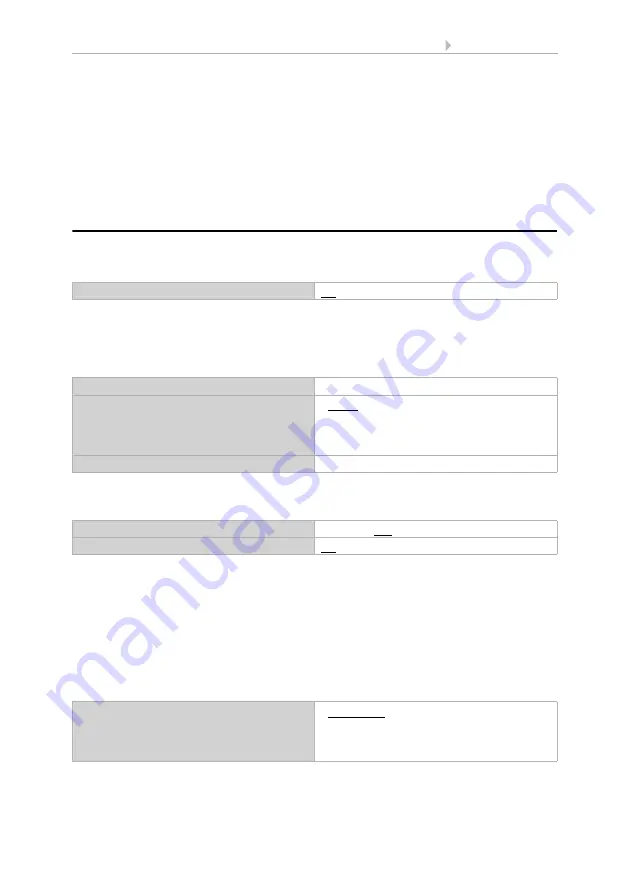
Use control

No • Yes

Maintain the

data received via object for setpoint, set-
point-actual difference, dimming increment 
and times

• never
• after power supply restoration
• after power supply restoration and 
  programming

Setpoint value in Lux

0...60000; 500

Send switching object

No • Yes

Regulation starts on

• movement
• reception of a start/stop-object
• reception of a start/stop-object or 
   movement

Summary of Contents for 70396

Page 1: ...Item numbers 70396 white 70696 jet black Sewi KNX L Pr Presence detector with brightness sensor EN Installation and Adjustment ...

Page 2: ......

Page 3: ...4 Commissioning 8 4 1 Addressing the equipment 8 5 Maintenance 8 6 Disposal 8 7 Transfer protocol 10 7 1 List of all communication objects 10 8 Parameter setting 19 8 1 Behaviour on power failure restoration of power 19 8 2 General settings 20 8 3 Motion detector 20 8 3 1 Master 1 2 3 4 21 8 3 2 Align communication between master and slave 25 8 4 Light control 26 8 5 Brightness Measurement 28 8 6 ...

Page 4: ...in this manual Safety advice Safety advice for working on electrical connections components etc DANGER indicates an immediately hazardous situation which will lead to death or severe injuries if it is not avoided WARNING indicates a potentially hazardous situation which may lead to death or severe injuries if it is not avoided CAUTION indicates a potentially hazardous situation which may lead to t...

Page 5: ...nputs in the form of communications objects can be used as inputs for the logic gates The output of each gate can be configured optionally as 1 bit or 2 x 8 bit 8 multi function modules computers for changing the input data by calculations by querying a condition or by converting the data point type Configuration is made using the KNX software ETS The product file can be down loaded from the Elsne...

Page 6: ...directives regulations and provisions for electrical installation Immediately take the device or system out of service and secure it against unintentional switch on if risk free operation is no longer guaranteed Assignments max 2000 Communication objects 230 Nominal voltage KNX 30 V SELV Power consumption KNX max 10 mA Connection KNX plug terminals Duration after bus voltage restoration until data...

Page 7: ...oundings designated for it Elsner Elektronik is not liable for any changes in norms and standards which may occur after publication of these operating instructions 3 Installation 3 1 Installation location and preparation Install and use only in dry interior rooms Avoid condensation The Sensor Sewi KNX L Pr is installed surface mounted on ceilings To detect the presence of persons make sure that th...

Page 8: ...NX L Pr is surface mounted but at the same time can also be screwed to a flush mounted socket If the Sensor Sewi KNX L Pr is installed on a flush mounted socket it must not con tain any wiring with 230 V 3 2 1 Layout of the circuit board 1 a b Long holes for mounting hole distance 60 mm 2 Brightness sensor 3 Presence sensor 4 Programming button 5 Programming LED 6 KNX terminal BUS 7 Cable bushing ...

Page 9: ...side 1 Brightness sensor 2 Presence sensor A Recess to open the housing A 2 Fig 4 Open the housing To do this carefully lift the cover from the skirting Start at the recess e g with a flat head screwdriver Fig 5 Lead the bus cable through the cable bushing in the skirting Fig 6 Screw the skirting to the ceiling Hole distance 60 mm 60 mm ...

Page 10: ...quipment The individual address is assigned via the ETS For this purpose there is a button with a control LED on the unit Fig 2 No 4 5 The equipment is delivered with the bus address 15 15 255 Another address can be programmed using the ETS 5 Maintenance As a rule it is sufficient to wipe the device with a soft dry cloth twice a year 6 Disposal After use the device must be disposed of in accordanc...

Page 11: ...9 Disposal Sensor Sewi KNX L Pr Version 26 10 2021 Technical Changes and Errors excepted ...

Page 12: ...tch 1 bit 131 Brightness sensor 2 threshold value 1 Delay from 0 to 1 Input WC 7 5 DPT_Time PeriodSec 2 bytes 132 Brightness sensor 2 threshold value 1 Delay from 1 to 0 Input WC 7 5 DPT_Time PeriodSec 2 bytes 133 Brightness sensor 2 threshold value 1 Switching output Output R CT 1 1 DPT_Switch 1 bit 134 Brightness sensor 2 threshold value 1 Switching output block Input WC 1 1 DPT_Switch 1 bit 136...

Page 13: ...reshold value 4 1 0 Input WC 1 1 DPT_Switch 1 bit 152 Brightness sensor 2 threshold value 4 Delay from 0 to 1 Input WC 7 5 DPT_Time PeriodSec 2 bytes 153 Brightness sensor 2 threshold value 4 Delay from 1 to 0 Input WC 7 5 DPT_Time PeriodSec 2 bytes 154 Brightness sensor 2 threshold value 4 Switching output Output R CT 1 1 DPT_Switch 1 bit 155 Brightness sensor 2 threshold value 4 Switching output...

Page 14: ...nding on setting 4 bytes 1158 Computer 3 Input I2 Input RWCT Depending on setting 4 bytes 1159 Computer 3 Input I3 Input RWCT Depending on setting 4 bytes 1160 Computer 3 Output O1 Output R CT Depending on setting 4 bytes 1161 Computer 3 Output O2 Output R CT Depending on setting 4 bytes 1162 Computer 3 Condition text Output R CT 16 0 DPT_String_ASCII 14 bytes 1163 Computer 3 Monitoring status Out...

Page 15: ...pending on setting 4 bytes 1183 Computer 6 Input I3 Input RWCT Depending on setting 4 bytes 1184 Computer 6 Output O1 Output R CT Depending on setting 4 bytes 1185 Computer 6 Output O2 Output R CT Depending on setting 4 bytes 1186 Computer 6 Condition text Output R CT 16 0 DPT_String_ASCII 14 bytes 1187 Computer 6 Monitoring status Output R CT 1 1 DPT_Switch 1 bit 1188 Computer 6 Block 1 block Inp...

Page 16: ... 1396 Logic input 6 Input WC 1 2 DPT_Bool 1 bit 1397 Logic input 7 Input WC 1 2 DPT_Bool 1 bit 1398 Logic input 8 Input WC 1 2 DPT_Bool 1 bit 1399 Logic input 9 Input WC 1 2 DPT_Bool 1 bit 1400 Logic input 10 Input WC 1 2 DPT_Bool 1 bit 1401 Logic input 11 Input WC 1 2 DPT_Bool 1 bit 1402 Logic input 12 Input WC 1 2 DPT_Bool 1 bit 1403 Logic input 13 Input WC 1 2 DPT_Bool 1 bit 1404 Logic input 14...

Page 17: ...ND logic 5 Block Input WC 1 1 DPT_Switch 1 bit 1431 AND logic 6 1 bit switching output Output R CT 1 2 DPT_Bool 1 bit 1432 AND logic 6 8 bit output A Output R CT 5 010 DPT_ Value_1_Ucount 1 byte 1433 AND logic 6 8 bit output B Output R CT 5 010 DPT_ Value_1_Ucount 1 byte 1434 AND logic 6 Block Input WC 1 1 DPT_Switch 1 bit 1435 AND logic 7 1 bit switching output Output R CT 1 2 DPT_Bool 1 bit 1436...

Page 18: ...OR logic 4 Block Input WC 1 1 DPT_Switch 1 bit 1459 OR logic 5 1 bit switching output Output R CT 1 2 DPT_Bool 1 bit 1460 OR logic 5 8 bit output A Output R CT 5 010 DPT_ Value_1_Ucount 1 byte 1461 OR logic 5 8 bit output B Output R CT 5 010 DPT_ Value_1_Ucount 1 byte 1462 OR logic 5 Block Input WC 1 1 DPT_Switch 1 bit 1463 OR logic 6 1 bit switching output Output R CT 1 2 DPT_Bool 1 bit 1464 OR l...

Page 19: ... 2 bytes 1536 Beweg sensor Master 1 Ausschalt verzögerung Eingang LSK 7 5 DPT_Ti mePeriodSec 2 Bytes 1537 Motion detector Master 1 Slave message Input WC 1 1 DPT_Switch 1 bit 1538 Motion detector Master 1 Slave cycle reset Output CT 5 1 DPT_Scaling 1 byte 1539 Motion detector Master 1 Block 1 Blocking Input WC 1 1 DPT_Switch 1 bit 1540 Motion detector Master 1 Central off Input WC 1 1 DPT_Switch 1...

Page 20: ...ing 1 byte 1559 Motion detector Master 3 Block 1 Blocking Input WC 1 1 DPT_Switch 1 bit 1560 Motion detector Master 3 Central off Input WC 1 1 DPT_Switch 1 bit 1561 Motion detector Master 4 Brightness threshold value on Input Output RWCT 9 4 DPT_Val ue_Lux 2 bytes 1562 Motion detector Master 4 Brightness threshold value off Input Output RWCT 9 4 DPT_Val ue_Lux 2 bytes 1563 Motion detector Master 4...

Page 21: ...Target actual difference Input Output RWCT 9 4 DPT_Val ue_Lux 2 bytes 1587 Light controller Reset time Input Output RWCT 7 5 DPT_Time PeriodSec 2 bytes 1588 Light controller Actuating variable Input Output R CT 5 1 DPT_Scaling 1 byte 1589 Light controller Switching Output R CT 1 1 DPT_Switch 1 bit 1590 Light controller Dimming Output R CT 3 7 DPT_Con trol_Dimming 4 bit 1591 Light controller Bright...

Page 22: ...he type and value of the test object Send delay after power up and programming for Measured values 5 s 2 h Threshold values and switching outputs 5 s 2 h Computer objects 5 s 2 h Logic objects 5 s 2 h Maximum telegram rate 1 message per second 5 messages per second 20 messages per second Use test object No Yes If test object is used Release object analysis at value 1 release at value 0 block at va...

Page 23: ...et the object type and value for the cycle reset input for the slave in the same way as for the cycle reset output for the master The slave can be blocked via the bus 8 3 1 Master 1 2 3 4 If the device is set as a master the additional master settings 1 to 4 will appear This enables the Sensor Sewi KNX L Pr to perform four different control functions for motion detection Activate the master in ord...

Page 24: ...cially lit room If the indoor light level is above the switch on limit value but below the switch off limit value and the motion is still ongoing or if another motion is detected before the end of the switch off delay then the switch off delay time period starts over Only when the light level exceeds the switch off limit value is the switch off delay no longer extended If the master output has det...

Page 25: ... the end of the motion then the light level must drop below the switch on limit value for motions to be detected again Settings for all types of motion detection The following settings can be made independent of the motion detection type i e for constant and brightness dependent motion recognition Define the output type and value As a result of the different types switchable lights 1 bit dimmer 1 ...

Page 26: ...y Set the master s output sending pattern In addition you can refer to a slave signal i e a signal from an additional motion de tector for controlling purposes The slave device periodically sends a 1 to the bus as long as a motion is detected The master receives this at the input object master slave message and evaluates the sla ve message as an own sensor message Furthermore the master has the po...

Page 27: ...itch off action it simultaneously sends a message to the bus via the master slave cycle reset This message can be received by the slave via the slave cycle reset in order to immediately send a message to the bus in the event of a motion detection The master receives the motion message without having to wait for the next slave transmission cycle Please note that object type and value for the slave ...

Page 28: ...p as the factory settings are always used until the first communication Set the setpoint value for the brightness in the room and specify whether besi des the dimming information defined below a switching object should also be sent Specify whether the light control is activated by presence of persons move ment and or by a start stop object For a regulation by presence of persons mo vement the devi...

Page 29: ...o be continued Regulation stops on movement reception of a start stop object reception of a start stop object or movement Object evaluation 1 start 0 stop 0 start 1 stop Object value prior to initial communication 0 1 Stop delay in seconds after the movement has ended 0 1800 120 Reaction to stop send nothing send off command send on command send value Value in 0 100 Send the dim command if the act...

Page 30: ...reading can be corrected in order to compensate for a dull or bright point of installation for the sensor Continue regulation after a waiting period at movement after waiting period at object reception after waiting period at object reception or after waiting period at movement after object reception at object reception or movement after waiting period Waiting period in seconds 5 72000 Standard va...

Page 31: ...hreshold value Set in which cases threshold values and delay times received are to be kept per object The parameter is only taken into consideration if the specification setting by object is activated further down Please note that the setting After power restoration and pro gramming should not be used for the initial start up as the factory settings are always used until the first call setting via...

Page 32: ...valid until first call 1 5000 200 Object value limit min in Lux 1 5000 Object value limit max in Lux 1 5000 Type of threshold change Absolute value Increase decrease Increment in Lux upon increase decrease change 1 2 5 10 20 50 100 200 500 1000 Hysteresis setting in absolute Hysteresis in of the threshold value for setting in 0 100 50 Hysteresis in Lux for absolute setting 0 5000 200 When the foll...

Page 33: ...ed Use switching output block No Yes Analysis of the blocking object At value 1 block At value 0 release At value 0 block At value 1 release Blocking object value before first call 0 1 Action when locking Do not send message send 0 send 1 Action upon release with 2 seconds release delay Dependent on the Switching output sends setting Switching output sends on change do not send message Status obje...

Page 34: ...o be kept per object Please note that the setting After power restoration and programming should not be used for the initial start up as the factory settings are always used until the first call setting via objects is ignored Night is recognised below Lux 1 1000 10 Hysteresis in Lux 0 500 5 Delays can be set via objects in seconds No Yes Switching delay on night none 1 s 2 h Switching delay on day...

Page 35: ...tion Output 1 E1 X Y Output 2 E2 X Y Transformation General Tolerance for comparison in the case of prerequisite E1 E2 0 4 294 967 295 Input type Selection options depending on the func tion 1 bit 1 byte 0 255 1 byte 0 100 1 byte 0 360 2 byte counter without math symbol 2 byte counter with math symbol 2 byte floating point 4 byte counter without math symbol 4 byte counter with math symbol 4 byte f...

Page 36: ...e depending on the type of output Output sends on change on change and after reset on change and periodically when receiving an input object when receiving an input object and periodically Type of change is only sent if on change is selected on each change on change to condition met on change to condition not met Send cycle if sent periodically 5 s 2 h 10 s Text if the condition is met Free text m...

Page 37: ...0 at the block entry means and what happens in the event of a block Output sends on change on change and after reset on change and periodically when receiving an input object when receiving an input object and periodically on change of only if calculations are transmitted for changes 1 Input range depending on the type of input Send cycle if sent periodically 5 s 2 h 10 s Formula for output A1 A1 ...

Page 38: ...le for AND and OR logic Each logic output may transmit one 1 bit or two 8 bit objects Determine what the out put should send if logic 1 and 0 Value before first call 0 1 Output pattern On block do not send anything send value On release as send pattern see above send current value immediately Use logic inputs Yes No Object value prior to first call for Logic input 1 0 1 Logic input 0 1 Logic input...

Page 39: ...ts Output value if logic 1 1 0 Output value if logic 0 1 0 Output value If block is active 1 0 Output value if monitoring period is exceeded 1 0 Object type Value 0 255 Percent 0 100 Angle 0 360 Scene call up 0 127 Output value object A if logic 1 0 255 100 360 127 1 Output value object B if logic 1 0 255 100 360 127 1 Output value object A if logic 0 0 255 100 360 127 0 Output value object B if l...

Page 40: ...ange of logic and periodically on change of logic to 1 and periodically on change of logic to 0 and periodically on change of logic object receipt on change of logic object receipt and periodically Send cycle if sent periodically 5 s 10 s 2 h Use block No Yes Analysis of the blocking object At value 1 block At value 0 release At value 0 block At value 1 release Blocking object value before first c...

Page 41: ... input 13 Logic input 13 inverted Logic input 14 Logic input 14 inverted Logic input 15 Logic input 15 inverted Logic input 16 Logic input 16 inverted Switching output night Switching output night inverted Brightness sensor switching output 1 Brightness sensor switching output 1 inverted Brightness sensor switching output 2 Brightness sensor switching output 2 inverted Brightness sensor switching ...

Page 42: ... OR logic connection inputs correspond to those of the AND logic In addition the following inputs are available for the OR logic Switching output AND logic 1 Switching output AND logic 1 inverted Switching output AND logic 2 Switching output AND logic 2 inverted Switching output AND logic 3 Switching output AND logic 3 inverted Switching output AND logic 4 Switching output AND logic 4 inverted Swi...

Page 43: ......

Page 44: ...mbH Control and Automation Engineering Sohlengrund 16 75395 Ostelsheim Phone 49 0 70 33 30 945 0 info elsner elektronik de Germany Fax 49 0 70 33 30 945 20 www elsner elektronik de Technical support 49 0 70 33 30 945 250 ...

Reviews: