


LIN101
RS232 / LAN INTERFACE
ELPRO Video Labs s.r.l.
Via della Praia 4/a FERRIERA di BUTTIGLIERA ALTA (TO) - ITALY
Tel. +39 0119348778 - FAX +39 0119348779
7
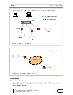
3 Slave and Master routing modes
The LIN101 routes the data in one of two modes as defined by the Routing Mode Setting:
•
In the Slave Routing Mode the LIN101 never sends any data transmission in the serial port -> Ethernet direction
before it receives some data from the remote station first (i.e. the data in the Ethernet -> serial direction). The
serial data received into the LIN101’s serial port before the remote station “contacts” the LIN101 is discarded. In
the Slave Mode the LIN101 will “work” with any station on the network that contacts it
•
In the Master Routing Mode the LIN101 does not wait for the remote station to send the data first and routes the
data in the serial -> Ethernet direction as soon as there is a data to be sent. The data is always sent to a
specific destination (as defined by the Destination IP-address and Destination Data Port Number Settings of the
LIN101). Also, the LIN101 only accepts the data sent from the remote station whose IP-address matches the
one set in the Destination IP-address. The LIN101 will discard the data sent from any other IP. Note, that data
port number of the sender is not verified so the data can be sent from any port.
3.1 Using Slave and Master Routing Modes
Use the Slave Routing Mode to network-enable serial devices that never send out the data by themselves but instead
are “polled” for data from the PC. Examples of such devices are time recorders, access control panels and other
“hardware terminals”.
Use the Master Routing Mode to network-enable serial devices that send out the data “spontaneously” i.e. without
waiting for the request from PC.
Also use the Master Routing Mode in cases when the serial data must flow independently in both directions (i.e. Ethernet
-> serial and serial -> Ethernet). This is the case, for instance, when you are creating a “network modem” that must pass
the data in both directions simultaneously.
3.2 Required network settings for the Slave and Master Routing Modes
In the Slave Routing Mode the LIN101 only “responds” to other stations on the network. When the LIN101 receives the
data from remote station it memorizes this station’s IP-address and data port number. When routing the data in the serial
-> Ethernet direction the LIN101 will reply to this IP-address and data port number. Therefore, the only network settings
that must be set in the Slave Routing Mode are the LIN101’s own IP-address and the Data Port Number.
This is true
even if there is a router between the remote station and the LIN101. You don’t have to set the Netmask
and Gateway IP when using the LIN101 in the Slave Routing Mod
e;
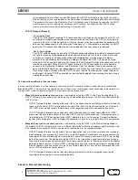
In the Master Routing Mode the LIN101 needs to be able to send the data to a predefined remote station at any time.
This means that not only LIN101’s own IP-address and Data Port Number must be set but also the Destination IP-
address and the Destination Data Port Number. If the destination remote station and the LIN101 are residing in different
network segments then the Netmask and Gateway IP-address must also be set.
3.3 Slave and Master routing modes vs. UDP/IP and TCP/IP transport protocols
UDP/IP and TCP/IP provide completely different data transmission so LIN101s behavior in the Slave and Master Routing
Modes is slightly different under UDP/IP and TCP/IP Transport Protocols.
•
UDP/IP Transport Protocol
o
Slave Routing Mode.
All UDP data packets arriving from any remote station and addressed to the Data Port of the LIN101
are routed to the serial port. For the serial -> Ethernet direction the LIN101 always sends the data to
the IP-address and the port number that were received in the last (latest) UDP packet. Once the
LIN101 receives a UDP packet from a different station it will start sending all its serial -> Ethernet data
to this new station. After power up and before the LIN101 receives the first UDP data packet the
LIN101 doesn’t have any IP-address and port number to send the data to so all the data received into
the LIN101’s serial port is simply discarded.
o
Master Routing Mode.
The LIN101 only accepts and routes to the serial port the data packets that have originated from the
remote station whose IP-address matches the one defined by the Destination IP-address Setting.
Source data port number need not match the one defined by the Destination Data Port Number Setting