background image


P


7.

8.

Photoe

. Optical A

Read volt

highest re

ƒ

  Su

ƒ

  Se

Lo
op
ve
Re

ƒ

  Ad

Re


. Terminal

electric

Alignment 

tage from m

eliability. 

upply powe
et Transmit

ook through
pposite unit

ertically (±10

eceiver sho

djust the Tr

eceiver's ho

l Arrangem

c Beam

monitor jack

er with cove

tter lens to r

h view finde

t is visible. (

0°) allowing

ould appear

ransmitter's 

orizontally a

ment 

m Detec

k with volt-m

r detached.

recover lens

r on both si

(Using the a

g the unit to
r on the view

horizontally

and verticall

ctor 

meter (digita


s by the vie
ide and line

adjuster, the

 work in all 

w finder of i

y and vertic

ly to get hig

l) to confirm

w finder. 

e-up optics h

e lens can m

the directio

nside middl

cally to get h
ghest voltag

m optical alig

horizontally 

move horizo

ons). The op

le mirror. 

highest volta

ge reading.  

E

gnment and

and vertica

ontally (±90

pposite Tran

age reading

EL-PB60 S

d to obtain t

ally until the

°) and 

nsmitter or 

g. Adjust the

the 


Summary of Contents for EL-PB60S

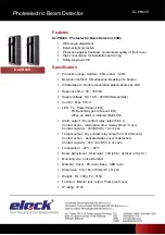
Page 1: ...25VDC Non polarity Current Max 57mA LED Tx Power Green LED Rx Sensitivity good Green LED When an alarm is initiated Red LED Alarm output Dry contact relay output form C Contact action Interruption time delay time 1 3 sec Contact capacity 30V AC DC 1A or Less Tamper output Dry contact relay output form N C Rx only Contact action Activated when cover is detached Contact capacity 30V AC DC 1A or Less...

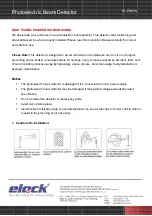
Page 2: ...e visibility ran ace fog occ lation m Detec nstructio ur photoelec installed P gned to dete sponsible fo by lightening tector is dam tector may b r or replace ge or possi ur frequent ctor on ctric beam d Please read ect intrusion or damage g abuse m maged if it i be damaged e any parts ble distance ly detector Th this Instruc n and to init injury or los misuse abn s connected d if the app e can se...

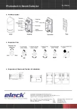
Page 3: ...P 2 3 4 Photoe Part Des Respons Expansio electric cription se Time on of Beam c Beam m and Posit m Detec tion of Inst ctor tallation E EL PB60 S ...

Page 4: ...ic Beam Detector EL PB60 S 5 Installation 6 Channel Setting This function is used for purpose of preventing cross talk or bypass of beams which may occur in line protection or 2 stacked protection Set beam channel ...

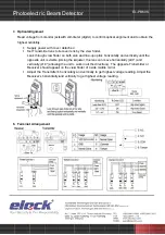
Page 5: ...m Detec k with volt m r detached recover lens r on both si Using the a g the unit to r on the view horizontally and verticall ctor meter digita s by the vie ide and line adjuster the work in all w finder of i y and vertic ly to get hig l to confirm w finder e up optics h e lens can m the directio nside middl cally to get h ghest voltag m optical alig horizontally move horizo ons The op le mirror h...

Page 6: ... as power machine is located nearby Tx and Rx Change the place for installation Unstable installation of Tx and Rx Stabilize Solied optics of Tx and Rx Clean the optics with a soft cloth Improper alignment Check and adjust again Small animals may pass through the 2 beams Set the response time longer 10 Dimensions Limited Warranty elock Products are warranted to be free from detect in material and ...

Reviews: