V.EPIR-A03052008
10
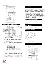
1. Open the top cover by loosing the screw at the bottom of
the unit as shown at
A
.
2. Mounting the wall bracket onto the wall at height of 2m
with screws as shown at
B
.
3. Insert the ball bracket (
C
) into the bottom back plate of the
unit and tighten up with screws.
4. Connect the signal cables to the corresponding terminal
accordingly.
0V, 12V
: 9 ~ 16 VDC, 12VDC recommended
ALARM
: Zone input for alarm panel (N.C/N.O)
TAMPER
: N.C loop for alarm panel
5. Insert the all unit after refit the top cover onto the wall
bracket.
6. There are 6 knockouts provided for the wall mounting
without the bracket. Ignore step 2 and 3 if installation
without using wall bracket.
7. Remove the PCB from the base. Mount the base on the
wall with selected position with at least 2 screws after
remove the knockouts (
D
).
8. Refit the PCB onto the base and replace the top cover,
apply the power supply to the detector and conduct a walk
test.
Wait approximate 1.5 minutes after applying 12VDC power for
the warm up and stabilize time. Conduct a testing with the
protected area cleared of all people. Walk test should be
conducted at least once a year to confirm proper operation and
coverage of the detector.
1. Wait until the LED is off.
2. Walk across the detection zones with a normal speed.
3. The LED will turn on whenever it detects a movement.
4. Allow 8-11 seconds between each test for the detector to
stabilize.
5. The LED display can be disabled by pulling off the jumper
at location J2 labeled as “ON/OFF”.
Use the sensitivity adjustment jumper (JP1) to select high / low
sensitivity. Placing on the jumper cap indicates HIGH
sensitivity selection; remove the cap for LOW sensitivity
selection.
The Pet Immunity system is being embedded into the board,
which is set to factory default setting.
2
1
WALK TEST
SENSITIVITY ADJUSTMENT
INSTALLATION INSTRUCTION
B
A
D
PET IMMUNITY
C
MOUNTING SETTING
COVERAGE PATTERN
ICT at work!
3
4
5
6
7
8
9


