background image

Version. 1.0 

8

¾


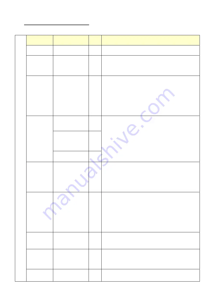
Structure of OSD settings: 


First Level 

Second Level 

Third 

Level

Operating Procedure 

Auto Adjust 


Press “UP” or “DOWN” to adjust H-phase & 
H-position & V-position clock automatically. 

Luminance 

Brightness 
Contrast 
Exit 


Press “UP” key to increase brightness, “DOWN” key to 
decrease brightness. 
Press “UP” key to increase contrast, “DOWN” key to 
decrease contrast. 

Geometry 

H. Position 
V. Position 
Clock 
Phase 
Exit 


Press “UP” key to shift screen right, “DOWN” key to 
shift screen left. 
Press “UP” key to shift picture upward, “DOWN” key 
to shift picture downward. 
Adjust sampling clock of analog to digital converter 
until clock is equal to pixel frequency of video input. 
By varying this “UP” “DOWN” control the exact 
sampling time within the pixel can be adjusted. 

9300K 
6500K 
5800K 


User Preset 

Red 
Green
Blue 
Exit 

Color 

Exit 


Press “UP” or “DOWN” to choose three types of color 
temperature 9300°k, 6500°k and user define. 

OSD 

H. Position 
V. Position 
OSD Timeout 
Exit 


Adjust OSD frame horizontal location, press “UP” key 
to shift frame right, “DOWN” key to shift frame left , 
timeout and preset OSD. 
Adjust OSD frame vertical location, press “UP” key to 
shift frame upward, “UP” key to shift frame 
downward , timeout and preset OSD. 

Language 

English 
French 
German 
Italian 
Spanish 
Japanese 
T. Chinese 
S. Chinese 


Press “UP” or “DOWN” to choose any one of the 
following language, English, French, Germany, Italy, 
Spain , Japanese, Traditional Chinese and Simplified 
Chinese. 

Recall 

Color Recall 
Recall All 
Exit 


Recall the default value. 

Miscellaneous 

Sharpness 
Display 
Information 
Exit 


Press “UP” key to increase sharpness, “DOWN” key to 
decrease sharpness. 

Main 
Menu 

Exit 


Summary of Contents for M467

Page 1: ...incorrect power voltage Do not exposure this unit in the rain or moisture environment to reduce the risk of fire or electric shock Content I Introduction 1 Features 1 Unpack the monitor 2 Installation...

Page 2: ...please contact our regional distributor for further information Features Optimal display resolution 1024 768 VESA 75 75 mm wall mount standard Durable and sturdy base design Optional 3 tracks Magneti...

Page 3: ...position Remove packing materials from inside of box Check accessory Please make sure all the accessory are included Standard Items a b c d e f Optional Items a b a MSR b 2nd display 8 4 a LCD Monitor...

Page 4: ...cement 1 DC JACK 2 DVI 3 VGA 4 USB B Type 5 Dual USB A Type 6 RS232 7 RJ45 RS232 To PC 1 Connect VGA cable from monitor to PC 2 Connect USB touch cable to PC 3 Connect DC plug to monitor and the other...

Page 5: ...tination location window 4 Click next from ready to install the program 5 Click next from setup type 6 Click finish when setup completed Calibration procedures 1 Double click POS Touch icon to run cal...

Page 6: ...Select Language 4 Select Install Serial or USB Touchscreen Driver 5 Click on Yes after Installation 6 Click on Finish Calibration procedures 1 Double click Elo Touchscreen icon to run calibration func...

Page 7: ...Version 1 0 6 MSR installation optional Components of MSR Kit 1 Slide the MSR into the right position of the System 2 Fasten the screws x2 Screws USB MSR...

Page 8: ...t it and read to adjust Press the MENU key to activate the On Screen Display OSD Press twice to turn off the OSD After 30 sec idle time the OSD screen will automatically turn off Power Use the power s...

Page 9: ...g time within the pixel can be adjusted 9300K 6500K 5800K User Preset Red Green Blue Exit Color Exit Press UP or DOWN to choose three types of color temperature 9300 k 6500 k and user define OSD H Pos...

Page 10: ...operation and call the nearest dealer or service center IV Support timing chart Timing Mode Reference Standard Resolution Pixel MHz FH KHz FV Hz Interlace H Polarity V Polarity Mode 1 VESA 1024 768 6...

Page 11: ...ch can be determined by turning the equipment off and on the user is encouraged to try to correct the interference by one or more of the following measures Reorient or relocate the receiving antenna I...

Page 12: ...ewing Angle 160 degrees V Input Video Format VGA Input Video signal connector D Sub 15 pins DVI D I O port DC JACK DVI VGA USB B USB A RS 232 RJ45 Power consumption 20W Horizontal 31 5 kHz 60 2 kHz In...

Reviews: