background image

33

MODEL 520

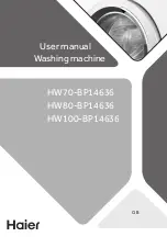
REPLACING THE FEED STITCH MOTOR

REPLACING THE FEED MOTOR

TO REMOVE:

1. Remove the front cover and rear covers (see page 6 and 8).

2. Remove the snap ring (E-3).

3. Remove the two setscrews and remove the feed motor.

TO INSTALL:

4. To install the feed motor, follow the above procedure in reverse.

NOTES:

Adjust the stretch stitch patterns (see page 18).

Snap ring (E-3)

Snap ring (E-3)

Feed motor

Setscrew

Access setscrew

through this hole

Summary of Contents for eXperience 520

Page 1: ...SERVICE MANUAL MODEL eXperience 520...

Page 2: ...IGZAG SYNCHRONIZATION 16 NEEDLE THREAD TENSION 17 STRETCH STITCH FEED BALANCE 18 REPLACEMENT AND ADJUSTMENT OF THE NEEDLE THREADER PLATE 19 CONNECTOR DIAGRAM 20 SELF DIAGNOSTIC TESTS 21 SELF DIAGNOSTI...

Page 3: ...Use a 11 blue tip needle Adjust the presser bar level to make the pressure stronger See mechanical adjustment Needle bar height See mechanical adjustment Needle to shuttle timing See mechanical adjus...

Page 4: ...1 Incorrectly threaded bobbin 2 Too much thread is around on the bobbin 3 Lint is stuck inside the bobbin holder 4 Thread quality is too low 5 Thread is jamming around the bobbin Thread bobbin correc...

Page 5: ...t Backlash lower shaft gear Eliminate the looseness See part removal and replacement driving motor DC motor Oil all moving parts P 14 P 28 P 36 7 Deformation pattern 1 Inappropriate feed balance 2 Ina...

Page 6: ...VER TO REMOVE 1 Remove the cap 2 Remove the setscrew A and remove the face cover TO INSTALL 3 Insert the three ribs and the hook on the face cover into the rear cover Tighten the setscrew A and attach...

Page 7: ...t the drop lever to the left and remove the three setscrews A remove the bed cover TO INSTALL 2 Set the drop lever to the left and install the bed cover Secure it in place with the three setscrews A S...

Page 8: ...your fingers and pull Do not pull on the lead wire as this may damage the contact sleeve inside the connector TO INSTALL 4 To install the front cover follow the above procedure in reverse NOTES TO CON...

Page 9: ...e rear cover indicated by the white arrows and the hook on the base 2 Remove the feed balancing dial 3 Remove the machine socket and then remove the front cover Remove the setscrews G and H from the r...

Page 10: ...7 2 Loosen the setscrews A B C D and E To remove the cover detach the presser foot lifter section first with the presser foot lifter in the down position TO INSTALL 3 Follow the above procedure in re...

Page 11: ...presser foot is raised the clearance between the presser foot and the needle plate should be 6 0 mm When the presser foot is lowered the edge of the foot and the feed dog window on the needle plate sh...

Page 12: ...not in the center of the needle plate hole when the straight stitch is selected or if the clearance between the needle and edge of the needle plate hole on both side is less than 0 2 mm when the stitc...

Page 13: ...the straight stitch pattern no 2 left needle position 3 Remove the bed cover 4 Turn the handwheel toward you and set the needle bar at the lowest position 5 Loosen the setscrews on the lower shaft ti...

Page 14: ...t the pattern simple zigzag Maximum zigzag width 4 Turn the handwheel toward you until the tip of hook meets the right side of the needle 5 Loosen the setscrew A 6 Adjust the height of the needle bar...

Page 15: ...l toward you and adjust the clearance between master needle and the point of the hook in the left and right needle position to 0 1 to 0 05 mm by moving the hook in the left and right by moving the hoo...

Page 16: ...3 Turn the lower shaft bushing eccentric bushing clockwise B if there is too much play in the shuttle hook Turn the lower shaft bushing eccentric bushing counterclockwise A if there is too little play...

Page 17: ...et the pressure dial at 3 and lower the presser foot 2 Turn on the power switch 3 Remove the bed cover 4 Turn the handwheel toward you to set the feed dog at the highest position 5 Loosen the setscrew...

Page 18: ...el toward you slowly with your hand until the needle start to sewing Loosen the setscrew and turn the upper shaft shield plate in the direction of A If the swing point is higher than 7 5 mm B If the s...

Page 19: ...et the thread tension dial to 4 and check the thread tension 2 Remove the front cover see page 7 3 Pull the adjusting plate spring A away from the lead screw B and adjust by turning the lead screw B I...

Page 20: ...follows ADJUSTMENT PROCEDURE 1 Turn the power switch on and select the stitch pattern 2 Set the slit of the feed balancing dial to the standard setting mark on the front cover 3 Put a piece of paper u...

Page 21: ...t TO ADJUST THE THREADER PLATE POSITION 1 If the hook on the threader plate touches the left or right side of the needle guide loosen setscrew C and adjust the hook position FIG 2 2 If the hook on the...

Page 22: ...m while pushing them toward the printed circuit board to unlock them NOTES TO CONNECT THE CONNECTORS 1 Be sure that the color of each connector corresponds to the color of the connector post on the pr...

Page 23: ...umber of the required test is indicated PRELIMINARY TEST Turn on the power switch If any of following problems occur take the recommended actions in the order they are shown The machine does not respo...

Page 24: ...s 01 for one second If you don t press the 16 button within 2 5 seconds the machine automatically reverts to normal sewing mode Press 01 button led displays 02 for one second Press 01 button led displ...

Page 25: ...Upper shaft sensor 08 Sewing speed sensor OPERATION Press 01 button led displays 06 for one second 1 Lower the buttonhole lever 2 Move the buttonhole lever back and forth Press the 01 button led displ...

Page 26: ...right and finally it shows FF when the le ver reaches the right most position When the foot control is not depressed led should display F0 to FF hexadecimal value When the foot control is fully depres...

Page 27: ...oot control CORRECT CONDITION Led indicates dc Machine runs at the speed set by the speed control lever Full left 80 100 SPM Full right 800 840 SPM DEFECTIVE CONDITION Machine does not run led display...

Page 28: ...transformer connectors pull them while pushing them toward the a board to unlock them TO INSTALL 4 To install follow the above procedure in reverse NOTES When installing board A in the machine The tra...

Page 29: ...ire on the board using the CS rings as shown Check to ensure that the slide volume moves smoothly back and forth REPLACING PRINTED CIRCUIT BOARD F TO REMOVE 5 Remove the front cover unit 6 Unplug the...

Page 30: ...DC motor and belt TO INSTALL 3 Lightly tighten the two screws 4 Put the motor belt on the pulley and adjust the belt deflection to about 7 to 9 mm by pressing the middle of the motor belt with your fi...

Page 31: ...Printed circuit board A Printed circuit board A case Fuse holder Fuse F2 AC250V 3 15A F3 AC250V 2 5A F1 AC250V 2 5A FUSE NO F1 F3 F2 PART NO 000 144 605 000 182 904 NOTES 1 Replace the printed circuit...

Page 32: ...cover see page 6 and 8 2 Remove the two screws and remove the machine socket TO INSTALL 3 To install the machine socket follow the above procedure in reverse NOTES Pull out the cord in front of the ar...

Page 33: ...remove the transformer Cut off the binder TO INSTALL 3 To install the transformer follow the above procedure in reverse NOTES Place the rear end of the transformer on the transformer support Slide the...

Page 34: ...tor TO INSTALL 4 To install the zigzag width motor follow the above procedure in reverse NOTES 1 The setscrew of zigzag rod should be tightened to 5 7 kg of torque 2 Check to ensure that the upper sha...

Page 35: ...overs see page 6 and 8 2 Remove the snap ring E 3 3 Remove the two setscrews and remove the feed motor TO INSTALL 4 To install the feed motor follow the above procedure in reverse NOTES Adjust the str...

Page 36: ...left until the led display changes from l to H 7 Next turn the adjusting screw to the right until the led display changes from H to l 8 Check the led When the clearance of the buttonhole foot is 1 4...

Page 37: ...just the clearance between the bobbin winder arm and the switch fixing plate to 0 7 to 13mm 3 Tighten the setscrew 4 Install the front cover TO CONFIRM Turn the power switch on The led displays when t...

Page 38: ...without routine oiling but you should still check for possible lubrication needs whenever servicing machines OIL Use good quality sewing machine oil at the points A B C D E F G H I J K indicated by th...

Reviews: