9
MECHANICAL ADJUSTMENT
BOBBIN TENSION
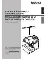
To check:
Set the bobbin in the bobbin case and pass the thread (cotton #50) through the tension spring.
The bobbin thread tension should be 45–55g when pulling the thread in the direction of (B).
If the tension is out of the range, adjust it as follows:
Adjustment procedure:
1. Turn the adjusting screw (C) in the direction of (D) when the bobbin thread tension is too tight.
2. Turn the adjusting screw (C) in the direction of (E) when the bobbin thread tension is too loose.
Cotton thread #50
(E)
(D)
(C)
(B)