background image

5

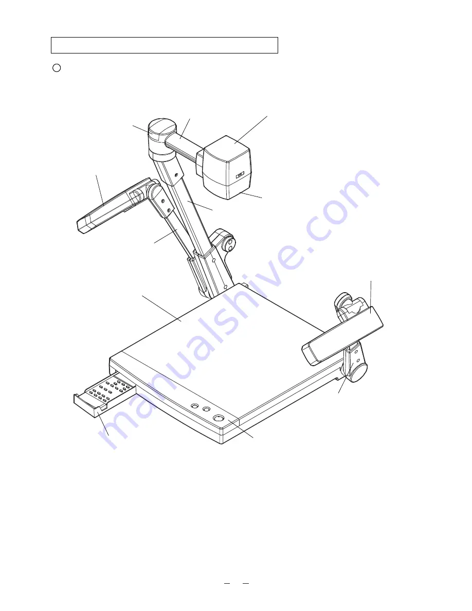
1. PART NAMES AND FUNCTIONS

Appearance

1. Stage

2. Column

3. Camera Head

4. Close-up Lens Holder

6. Lighting Arm (L)

7. Front Operation Panel

8. Remote Control Storage

Compartment

9. Infrared Sensor

5. Lighting Unit

(Attach this holder for normal
use. Swing away this holder for
viewing a far-away object.)

6. Lighting Arm (R)

5. Lighting Unit

10. Camera Head Arm

Summary of Contents for EV-2000AF

Page 1: ...VISUAL PRESENTER INSTRUCTION MANUAL Please read this instruction manual carefully before using this Visual Presenter and keep it for future reference ...

Page 2: ...tended to operate from battery power or other sources refer to the operating instructions Grounding or Polarization This product may be equipped with either a polarized 2 wire AC line plug a plug having one blade wider than the other or a 3 wire grounding type plug a plug having a third grounding pin The 2 wire polarized plug will fit into the power outlet only one way This is a safety feature If ...

Page 3: ...STIC ENVIRONMENT THIS PRODUCT MAY CAUSE RADIO INTERFERENCE IN WHICH CASE THE USER MAY BE REQUIRED TO TAKE ADEQUATE MEASURES INFORMATION This equipment has been tested and found to comply with the limits for a Class A digital device pursuant to Part 15 of the FCC Rules These limits are designed to provide reasonable protection against harmful interference when the equipment is operated in a commerc...

Page 4: ...ons Temperature 5 C 40 C 41 F 104 F Humidity 30 85 No condensation Use a soft dry cloth for cleaning Do not use any volatile solvent such as thinner or benzine Do not directly point the camera lens into the sun or the camera may be damaged Caring for the batteries If the Presenter is not used for a long time take out the batteries from the case Do not use rechargeable Ni Cd batteries Do not use ne...

Page 5: ...inted material 12 Convenient use of the camera 13 Storing the Presenter 14 5 VARIOUS FUNCTIONS 15 Lighting 15 Zoom 15 Enlarging the image 15 Focus 16 Nega posi conversion 17 Color B W selection 18 Iris 18 6 RS 232C SPECIFICATIONS 19 Setting up 19 Cable connection 20 RS 232C connector specifications DSUB 9P 20 Table of the communication commands 21 Data format specifications 22 Transmission specifi...

Page 6: ...4 Close up Lens Holder 6 Lighting Arm L 7 Front Operation Panel 8 Remote Control Storage Compartment 9 Infrared Sensor 5 Lighting Unit Attach this holder for normal use Swing away this holder for viewing a far away object 6 Lighting Arm R 5 Lighting Unit 10 Camera Head Arm ...

Page 7: ...UT S Video mini DIN 4P Composite Video RCA pinjack BNC 15 Power Switch POWER Name Function ReferencePage 13 Power Cord Receptacle AC IN To connect to the power cord 14 AC Outlet To supply power up to 400W Not interlocked with the power switch 15 Power Switch POWER To turn ON OFF the power supply 16 Video out Terminal To connect to a TV monitor or the like OUTPUT S VIDEO VIDEO S Video mini DIN4P Co...

Page 8: ...light 23 TELE To zoom in 24 WIDE To zoom out 25 NEAR To move the focus near 26 FAR To move the focus far 27 AF To focus automatically 28 IRIS NORMAL To reset the auto iris to the initial setting 29 IRIS OPEN To open the auto iris 30 IRIS CLOSE To close the auto iris P 15 P 15 P 17 P 18 P 15 P 15 P 15 P 16 P 17 P 16 P 17 P 16 P 18 P 18 P 18 Wireless Remote Control POSI NEGA COLOR B W LAMP TELE FAR ...

Page 9: ...umination of AC power discharge tube such as a fluorescent or a mercury lamp Using the unit with the shutter selection switch set to 50 may reduce the flickering This switch is factory set to 60Hz 32 Output Terminal USA ELMO USA Tech Support 800 947 3566 for further assistance Others Call to ELMO CANADA Canada or the ELMO exclusive distributors 9 8 7 6 5 4 3 2 1 1 2 3 4 5 6 7 8 9 VIDEO OUT GND NC ...

Page 10: ...Approx 7 m 23 ft or less from the light receiving area front of the wireless remote control Angle Approx 30 degrees or less from the light receiving area of the wireless remote control rightward leftward upward and downward respectively Preparation Remove the battery case cover by pressing downward on the mark part in the direction as indicated by the arrow Install 2 pcs of batteries type R03 AAA ...

Page 11: ...ed Note Unless the column is fully raised up it may not be locked when it is fallen 2 Raise the lighting arm R unit and turn the camera head to direct the lens unit to the stage 3 Turn the lighting unit 5 Plug the power cord into the power cord receptacle of the Presenter and the the AC outlet 4 Open the lighting arm unit and the lighting unit ...

Page 12: ...inal Use the supplied RCA video audio cable or a BNC cable available on the market Either the RCA jack or the BNC jack can be used Connection to the S video in terminal Connect the S video out terminal mini DIN 4P of the Presenter to the S video in terminal of the monitor TV with an S video cable available on the market If the equipment to be used is provided with a Y C separate connector a conver...

Page 13: ...size using the zoom buttons TELE WIDE on the operation panel or wireless remote control while watching the image on the TV monitor 3 Press the auto focus button AF on the front operation panel or remote control for focusing Note The auto focus function works up to a height of approx 15 cm 5 9 in above the stage surface on the maximum side of the zoom TELE when a close up lens is attached Simple st...

Page 14: ...be photographed When the camera head unit is set in the horizontal position wall view distant view etc can be photographed When the object is far away open the close up lens holder to your side Reference The focus can be achieved from 0 5 m 20 in to Convenient use of the camera Close up lens holder ...

Page 15: ...he lens may be damaged 3 Turn the lighting unit to the position shown in the right figure Note Be sure to return the lighting unit to its original position If it is in any other position when it is put away the lighting unit may be damaged 2 Close the lighting unit and the lighting arm unit 1 Turn OFF the power switch and unplug the power cord and the video cable 5 Raise up the column once and the...

Page 16: ...on panel or wireless remote control and the image will gradually be enlarged Note Within the electronic zoom range the image quarity is degraded Some documents objects may have conspicuous lateral stripes Press the zoom button WIDE on the front operation panel or wireless remote control and the image will gradually be reduced Reference Switching of the electronic zoom ON OFF can be swiched by pres...

Page 17: ...ront operation panel Remote control TELE FAR NEAR WIDE ZOOM FOCUS Front operation panel Remote control However the objects listed below may not be brought into focus in the auto focus mode In these cases use the manual focus mode Objects bearing little contrast Objects with fine repeated patterns such as lateral stripes and cross stripes Objects glittering or reflecting strong light Objects with b...

Page 18: ...orks up to a height of approx 15 cm 5 9 in above the stage surface on the maximum side of the zoom TELE when a close up lens is attached Nega posi conversion To show a negative film Press the posi nega conversion button POSI NEGA on the wireless remote control and the image will be converted accordingly To return to the normal POSI mode press the posi nega conversion button POSI NEGA again POSI NE...

Page 19: ...lor B W selection button COLOR B W again POSI NEGA COLOR B W LAMP Remote control Iris The auto iris can be manually adjusted To open the iris press the iris button OPEN To close the iris press the iris button CLOSE When the NORMAL button is pressed the setting is reset to the initial setting Note If the screen looks dark press the iris button OPEN on the wireless remote control to adjust the brigh...

Page 20: ...xt page Note To protect the Presenter and the PC be sure to turn OFF all the power switches of all equipment before connecting 2 Start the PC and set the communication mode of the RS 232C to the communication mode of the Presenter Note For the information how to set the communication mode of the RS 232C refer to the instruction manual of the PC 3 Start the PC program to operate the Presenter 4 Con...

Page 21: ...ed Data Transmitted Data Data Terminal Ready Signal Ground Data Set Ready Request To Send Clear To Send Direction of data Visual Presenter PC 5 4 3 2 1 9 8 7 6 1 2 3 4 5 6 7 8 9 CD TXD RXD DTR SG DSR RTS CTS RI CD RXD TXD DTR SG DSR RTS CTS RI CI 1 2 3 4 5 6 7 8 9 DSUB 9P Female 5 4 3 2 1 9 8 7 6 Visual Presenter side DSUB 9P DOS V side DSUB 25P ...

Page 22: ... adjust the Zoom Iris adjustment Command to adjust the Iris Lighting selection Command to select the Lighting Nega Posi conversion Command to convert Nega Posi Color B W selection Command to select Color B W Enlarged image movement 0 OFF 1 ON MA 0 OFF 1 ON LL 0 DF Electronic image enlargement Command to enlarge the image to double the center area of the image Local lockout Command to invalidate th...

Page 23: ...ing to receive correctly When the communication format is correctly received the Presenter sends ACK Normal Acknowledgement 06H Transmission Command PC Visual Presenter Each operation command is executed in ASCII code and transmitted in a set of 7 bytes as follows S T X E T X Command PC Visual Presenter ACK Data Parameter 02H 03H 06H Response data format Visual Presenter PC Status request format P...

Page 24: ...1 bit Parity bit None X parameter None Baud rate Communication speed 9600bps Connection If the RS 232C cable is not correctly connected between the Presenter and the PC no acknowledgement is transmitted Connect the RS 232C cable correctly and fix it firmly with the connector set screws before the operation ...

Page 25: ...witch and then turn ON the power switch Out of focus The object is too close to the lens Check if it does not stand higher than 15 cm 5 9 in above the stage surface Zoom is set at TELE after focusing at WIDE angle Focus on the point of max TELE In the auto focus focusing is difficult in some cases The lamp is not quickly turned ON For protection purposes the lamp is turned ON after preheating for ...

Page 26: ...from the stage surface 0 5m 20 in with the camera facing sideways and with no close up lens Focusing Auto manual Iris Auto with level adjustment Image pick up element 1 3 Interline transfer CCD Effective picture element 768 H x 494 V Total picture elements 811 H x 508 V approx 410 000 pixels Image signal processing Digital signal processing DSP Internal Resolution More than 470 TV lines Y signal w...

Page 27: ... and weight are approximate Trademark Acknowledgements ELMO are registered trademarks of ELMO CO Ltd Item Specifications Lighting High frequency lighting mode Model FPL9EX N Name Quantity 1 1 1 2 1 Power cord Video cable Infrared wireless remote controller RCW 402 Batteries Type R03 AAA Instruction manual ...

Page 28: ...Elmo Mfg Corp 1478 Old Country Road Plainview NY 11803 5034 Tel 516 501 1400 Fax 516 501 0429 E mail elmo elmousa com Web http www elmousa com Canada Elmo Canada Mfg Corp 44 West Drive Brampton Ontario L6T 3T6 Tel 905 453 7880 Fax 905 453 2391 E mail info elmocanada com Web http www elmcanada com Germany Elmo Europe G m b H Neanderstr 18 40233 Düsseldorf Tel 0211 376051 Fax 0211 376630 E mail elmo...

Reviews: