Technical Support Line +44 (0)23 9269 6638 (Option 3) POE-MINIPOD PAK200793_01A Nov 2016 © 2016 Elmdene International Ltd
C
ONNECTIONS
INPUT
PoE802.3at connection from PoE+ source
OUTPUT
PoE802.3at connection to PD
FAULT:
Relay output for PoE+ fail. Open if loss of PoE+.
BATT +, -
Connection to standby battery. Use cables provided (Observe polarity)
I
NSTALLATION
I
NSTRUCTIONS
This unit is only suitable for installation as permanently connected equipment. This PSU is
SUITABLE
for external
installation. This unit must be fed from a PoE802.3at power source.
Mounting
1)
Mount securely in correct orientation (RJ45 glands facing downwards) using the wall brackets provided
Power Up
2)
Attach suitable cable from PoE+ source to INPUT RJ45 connector
3)
Attach suitable cable between PD and OUTPUT RJ45 connector
4)
Connect charged 12V 7Ah VRLA battery using cables provided
NOTE:
ensure correct polarity of battery connections:
+ve
use
Red
lead,
-ve
use
Black
lead.
5)
Observe RED LED is ON when PoE+ is present
6)
Observe PD indicates power is present
7)
Remove INPUT cable from POE-MINIPOD and observe PD continues to indicate power is present
8)
Reconnect INPUT cable
Signalling
9)
Connect fault output to appropriate inputs of Control and Indicating Equipment (CIE) if required.
10)
Close cover and secure using fastening key provided.
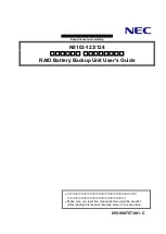
To PD
e.g. PoE Camera
To Switch / PoE+ source
Fuse
Battery connection
+ve / -ve
Fault
Output
OUTPUT (pre-wired)
INPUT (pre-wired)