Page 3
2000000498 (Rev. A - 01/22)
EZWSSMJO_2A
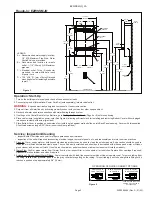
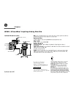
Rough-In: EZWSSMJO
Figure 1
Operation: Start-Up
1. Turn on the building water supply and check all connections for leaks.
2. Connect plug-end of International Power Cord Set (sold separately) into electrical outlet.
WARNING:
Exposed electrically energized components. Use extreme caution.
3. Purge air from all water lines by activating proximity sensor with your hand or other opaque object.
4. Recheck all water and drain connections with water flowing through system.
5. If setting up the Control Board for the first time, go to Setting the Control Board (Page 4 or 5) before continuing.
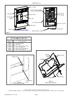
6. Place cable clamp (supplied)on power cord (See Figure 4) allowing sufficient slack for installing and removing Bottom Cover with cord pluged
in and secure clamp with screw (provided).
7. Place Bottom Cover in position on underside of unit with long tab against wall and slide up into Back Panel opening. Secure with two supplied
Allen Head screws using a 5/32” (4mm) hex wrench (not provided).
FINISHED FLOOR
FINISHED
WALL
A
B
C
D
D
D
D
D
D OPTIONAL
(3 PL)
ACTIVATION
SENSOR
9-1/2”
(241mm)
25-7/16”
(647mm)
17-15/16”
(455mm)
7”
(178mm)
7”
(178mm)
8-3/16”
(208mm)
5-3/8”
(136mm)
2-7/8”
(73mm)
1-3/8”
(35mm)
32-15/16”
(837mm)
34-7/16”
(875mm)
46-7/16”
(1179mm)
40-1/4”
(1022mm)
33-1/2”
(850mm)
30-1/16”
(763mm)
8-7/8”
(225mm)
28”
(712mm)
27”
(685mm)
6-1/4”
(159mm)
3-1/16”
(78mm)
12”
(305mm)
LEGEND:
A = Recommended water supply location;
1/2” (IPS Maximum Pipe Size. Water
Shut-off Valve not provided.
B = Recommended location for waste
outlet. 1-1/4” (32mm) O.D. Maximum
pipe size.
C = Electrical outlet, Three (3) conductor
grounded. Locate within safe reach
of power cord.
D = 7/16” x 3/4” (11.1mm x 19mm) Obround
mounting holes for fastening backplate
to wall.
Service: Inspection/Cleaning
•
Inspect Bottle Filler twice each year for proper operation and performance.
•
Inspection of the unit will require disconnecting electrical supply, removal of panels, etc. and reassembly and return to service practices.
1. Cleaning: Warm, soapy water or mild household cleaning products can be used to clean the exterior panels. Extra caution should be used to
clean the mirror finished stainless steel panels. They can be easily scratched and should only be cleaned with mild soap and water or Windex
glass cleaner and a clean, soft cloth. Use of harsh chemicals or petroleum based or abrasive cleaners will void the warranty.
2. Water Flow: Confirm proper water flow. If water flow is slow, inspect filter or inline strainer for restriction. Replace filter cartridge if required.
Disassemble inline strainer and clean if required.
3. Actuation of Quick Connect Water Fittings: Cooler is provided with lead-free connectors which utilize o-ring water seal. To remove tubing from
the fitting, relieve water pressure, push in on the gray collar before pulling on the tubing. To insert tubing, push tube straight into fitting until it
reaches a positive stop, approximately 3/4” (19mm).
B
C
A
SIMPLY PUSH IN
TUBE TO ATTACH
TUBE IS SECURED
IN POSITION
PUSH IN COLLET
TO RELEASE TUBE
OPERATION OF QUICK CONNECT FITTINGS
PUSHING TUBE IN BEFORE
PULLING IT OUT HELPS TO
RELEASE TUBE
OPERATION OF QUICK CONNECT FITTINGS
SIMPLY PUSH IN
TUBE TO ATTACH
TUBE IS SECURED
IN POSITION
PUSH IN COLLET
TO RELEASE TUBE
PUSHING TUBE IN BEFORE
PULLING IT OUT HELPS TO
RELEASE TUBE
A
B
C
Figure 2


