background image

Page 2

Elkay Manufacturing Company 


(630) 574-8484 


2000000696 (Rev. A - 07/22)

ECH8GRN_1C           

1. Safety  . . . . . . . . . . . . . . . . . . . . . . . . . . . . . . . . . . . 3

1.1 General . . . . . . . . . . . . . . . . . . . . . . . . . . . . . . 3
1.2  Safety Alert Symbol. . . . . . . . . . . . . . . . . . . . . 3
1.3 Definitions . . . . . . . . . . . . . . . . . . . . . . . . . . . . 3
1.4  Personal Safety. . . . . . . . . . . . . . . . . . . . . . . . 3
1.5  Property Damage  . . . . . . . . . . . . . . . . . . . . . . 5

2.  General Information. . . . . . . . . . . . . . . . . . . . . . . . 5

2.1  Installation / Use & Care . . . . . . . . . . . . . . . . . 5
2.2 Disclaimer . . . . . . . . . . . . . . . . . . . . . . . . . . . . 5
2.3  Serial Number Location  . . . . . . . . . . . . . . . . . 5
2.4  Contact Information. . . . . . . . . . . . . . . . . . . . . 5
2.5  Notice of Changes  . . . . . . . . . . . . . . . . . . . . . 5
2.6 Warranty . . . . . . . . . . . . . . . . . . . . . . . . . . . . . 5

3.  Installation Preparation - Read Before  


Beginning Installation . . . . . . . . . . . . . . . . . . . . . . 7

4.  Tools and Supplies  . . . . . . . . . . . . . . . . . . . . . . . . 7

4.1  Tools Required  . . . . . . . . . . . . . . . . . . . . . . . . 7
4.2  Installer-Supplied Parts. . . . . . . . . . . . . . . . . . 7
4.3  Tools/Items required but not provided. . . . . . . 7

5. Ratings  . . . . . . . . . . . . . . . . . . . . . . . . . . . . . . . . . . 7

5.1  ECH8GRN Series . . . . . . . . . . . . . . . . . . . . . . 7

6. Preparation . . . . . . . . . . . . . . . . . . . . . . . . . . . . . . . 8

6.1  General Information  . . . . . . . . . . . . . . . . . . . . 8

7.  Installation: Electrical Connection . . . . . . . . . . . . 8
8. Start-Up

.  . . . . . . . . . . . . . . . . . . . . . . . . . . . . . . . . . 9

9. Service  . . . . . . . . . . . . . . . . . . . . . . . . . . . . . . . . . . 9

9.1  Service: Adjustments  . . . . . . . . . . . . . . . . . . . 9

9.1.1  Temperature Control  . . . . . . . . . . . . . . . 9

9.2  Service: Inspection/Cleaning  . . . . . . . . . . . . . 9

9.2.1  Condenser Fan Motor  . . . . . . . . . . . . . . 9
9.2.2 Ventilation  . . . . . . . . . . . . . . . . . . . . . . . 9

9.2.3  Waterflow

. . . . . . . . . . . . . . . . . . . . . . . . 9

9.2.4 Lubrication . . . . . . . . . . . . . . . . . . . . . . . 9
9.2.5  Actuation of Quick Connect Water  

 Fittings . . . . . . . . . . . . . . . . . . . . . . . . . . 9

Table of Contents

Summary of Contents for ECH8GRN

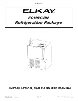
Page 1: ...ECH8GRN_1C 630 574 8484 Elkay Manufacturing Company 2000000696 Rev A 07 22 Page 1 ECH8GRN Refrigeration Package INSTALLATION CARE AND USE MANUAL...

Page 2: ...nstallation Preparation Read Before Beginning Installation 7 4 Tools and Supplies 7 4 1 Tools Required 7 4 2 Installer Supplied Parts 7 4 3 Tools Items required but not provided 7 5 Ratings 7 5 1 ECH8...

Page 3: ...Symbol and followed by a signal word such as WARNING or CAUTION 1 3 Definitions DANGER The signal word that indicates a hazard with a high level of risk which if not avoided will result in death or s...

Page 4: ...any maintenance make sure the unit is unplugged and circuit breakers are turned OFF Prior to installation test for live circuits or wiring inside the wall before cutting or drilling into the wall Fai...

Page 5: ...e installed properly by trained service person 2 2 Disclaimer The information contained in this Installation Use Care Manual is given free of charge It is based upon technical data which we believe to...

Page 6: ...4 261mm 17 3 8 441mm 1 3 4 95mm REF C D 1 3 8 35mm 2 50mm A B 13 1 4 338mm 1 25mm 3 3 4 57mm LEGEND A 1 4 O D TUBE WATER OUTLET B 1 4 O D TUBE WATER INLET C TEMPERATURE ADJUSTMENT D ELECTRICAL USES HF...

Page 7: ...uce risk of water damage Thoroughly flush all water lines and fittings of all foreign matter before connecting to chiller If inlet pressure is above 100 psig 0 69 MPa a pressure regulator must be inst...

Page 8: ...louvers on each side of chiller When mounting unit in a cavity or behind a wall maintain a minimum space of 4 102mm on each side 4 102mm on the top and a depth of 12 305mm 6 Water inlet is 1 4 6 mm O...

Page 9: ...ces 9 2 1 Condenser Fan Motor Visually check and confirm the condenser fan turns freely If the condenser fan does not spin freely have an authorized service personnel to check and replace the fan 9 2...

Page 10: ...ring Diagram TUBE IS SECURED IN POSITION SIMPLY PUSH IN TUBE TO ATTACH PUSH IN COLLET TO RELEASE TUBE PUSHING TUBE IN BEFORE PULLING IT OUT HELPS TO RELEASE TUBE Operation of Quick Connect Fittings Fi...

Page 11: ...ll correspondence pertaining to any of the above wa ter chiller or orders for repair parts MUST include model number and serial number of chiller name and part number of replacement part Evaporator Re...

Reviews: