background image

Page 4

M1XRF2H Installation Manual

General Installation and Setup

1. Mounting

 - Two (2) #6 x 1/2" screws (not provided), one on each side of the housing should be used for mounting.  The

receiver connects to the M1's Keypad data bus and may be remotely located up to several thousand feet away from the
control.  Mounting inside a metal enclosure or on metalized wallpaper is NOT RECOMMENDED!   Try and mount at least
10 feet away from any electrical device that generates noise including the M1 Control as electrical noise may reduce the
receiver sensitivity.  For increased signal coverage or redundancy additional M1XRF Receivers (up to 11 max.) may be
connected to the same M1 Controller.   See Appendix C.

2. Wiring Connections

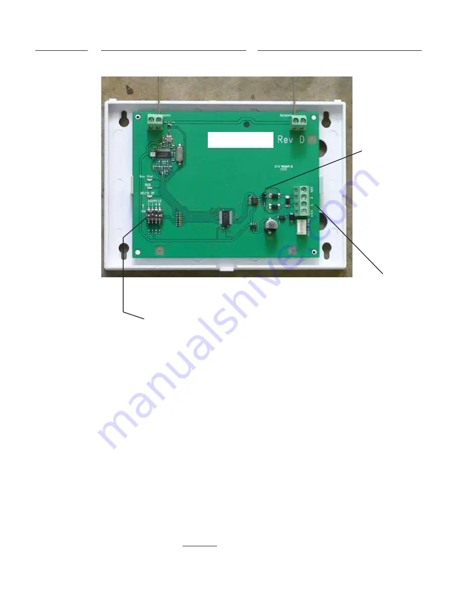
 - Before making any wiring connections, turn the power Off on the Control Panel.  Connect

ter12V, A, B, and Neg from the receiver to the M1's Keypad Data Bus (terVKP, Data A, Data B, & Neg).


NOTE: Refer to the M1 Installation Manual and the M1DBH information in this manual about proper

connections of data bus devices with multiple homerun cables.

3. Antenna Installation

The receiver is supplied with two (2) antennas.  These should be installed into the top locations marked Antenna.  Dual
antennas ensure signal diversity which helps eliminate RF dead spots.

NOTE: Each antenna location has a two (2) position screw terminal block.  MAKE SURE to insert and tighten the
antennas into the screw terminals marked ANTENNA.  Do not use the adjacent screw terminal.

INSTALL UNIT   *   SET ADDRESS AND OPTION JUMPERS   *   ACTIVATE M1 BUS ENROLLMENT PROCESS

RS-485

Data Bus

Connections

Data Bus Address Switches

Dual Antennas

Antenna 2

NOTE: Jumper JP1makes it convenient to terminate the RS-485 Data Bus if this is the last installed device.

ELK-M1XRF2H

Antenna 1

ELK-M1XRF2H

JP1 Bus

Terminating

Jumper

Summary of Contents for ELK-M1XRF2H

Page 1: ...S Hwy 70 West Hildebran NC 28637 828 397 4200 828 397 4415 Fax http www elkproducts com IMPORTANT NOTE ELK M1G and M1EZ8 Controls SHOULD have application firmware ver 5 1 24 or higher to be compatible...

Page 2: ...or antenna have a quality outdoor antenna installed Reorient the receiving antenna until interference is induced or eliminated Move the receiver away from the security control Move the antenna leads a...

Page 3: ...rollment data gets stored in the control panel not in the receiver s This provides two advantages 1 Multiple redundant receivers can be deployed in a building and a transmitter only need be enrolled o...

Page 4: ...nect terminals 12V A B and Neg from the receiver to the M1 s Keypad Data Bus terminals VKP Data A Data B Neg NOTE Refer to the M1 Installation Manual and the M1DBH information in this manual about pro...

Page 5: ...plicity installers are encouraged to set the data bus address of the first M1XRF Receiver if there are multiple Receivers to the starting zone ID as depicted in Tables 1 1 and 1 2 NOTE ELK strongly re...

Page 6: ...e ELK key then press 9 or scroll up to display 9 Installation Programming Press the RIGHT arrow key to select this menu The Installer Program Code PIN must be entered to access this menu 2 Enter the I...

Page 7: ...or the ElkRP Remote Programming software The following pages document the options and steps for programming from the keypad Transmitter RF Level Checking Signal Strength Wireless transmitters send mu...

Page 8: ...ing zone option WZnxxx 04 Enable Option 2 to YES Use Enroll Method 1 Use Enroll Method 2 Use Enroll Method 3 NOTE Program Zone Def as KEYFOB Each button can be assigned a functionality under SubMenu 4...

Page 9: ...kRP software to program the Xmtr ID Loop and any viable options Wall Transmitter 6 Button Ademco Part 5878 Enter manual by typing in the Xmtr ID or use a modified version of Enroll Method 3 To utilize...

Page 10: ...456789012345678901234567890121234 123456789012345678901234567890121234 123456789012345678901234567890121234 123456789012345678901234567890121234 123456789012345678901234567890121234 123456789012345678...

Page 11: ...456789012345678901234567890121234 123456789012345678901234567890121234 123456789012345678901234567890121234 123456789012345678901234567890121234 123456789012345678901234567890121234 123456789012345678...

Page 12: ...2 Zn 17 32 Data Bus Addr 3 Zn 33 48 Starting Zn ID 49 Data Bus Addr 4 Zn 49 64 M1XRF Cells marked indicate a Reserved Address which can only be used for wireless zones Cells marked RRF indicate bus ad...

Page 13: ...r 11 Zn 161 176 M1XRF Data Bus Addr 2 Zn 17 32 Data Bus Addr 3 Zn 33 48 Data Bus Addr 4 Zn 49 64 Data Bus Addr 5 Zn 65 80 Data Bus Addr 6 Zn 81 96 Data Bus Addr 7 Zn 97 112 Data Bus Addr 8 Zn 113 128...

Page 14: ...13 128 Zones 129 144 Zones 145 160 Zones 161 176 Zones 177 192 Zones 193 208 Bus Addr x Bus Addr 2 Bus Addr 3 Bus Addr 4 Bus Addr 5 Bus Addr 6 Bus Addr 7 Bus Addr 8 Bus Addr 9 Bus Addr 10 M1XIN or Key...

Page 15: ...Updates directory This is where RP looks for all update files 7 Click on the check box for Update If Reprogram or Rollback is displayed the firmware file is the same as OR older that what is in the c...

Page 16: ...Page 16 M1XRF2H Installation Manual...

Reviews: