Elite Screens ezFrame Plus Series User Manual Download Page 3

Rev.041014-JA   


www.elitescreens.com 


Push

Push

( fig.2)

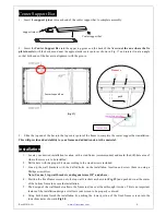
Insert the exposed ends of the joint connectors 
into the short (vertical) frame and align the four 
corners so that they meet at perfect right angles

Tension Rod (Horizontal) x 4 

Tension Rod (Vertical) x 2 

4.


Join   all   four   frame   parts   together   following   the   steps   shown   below.   

(Fig.2)


                Note:   When   assembled,   please   push   simultaneously   the   two   ends   of   the   long   frames.


Attaching the screen material to the frame 

1. Unroll the screen material and lay it down on a clean surface.    Then insert the tension rods separately into the 
edges of all four corners of the material 

(see fig.3) 


M5

×

15 screws 


(Fig. 3) 

Screen Material 

Screen Material 

push 

push 

push 

push 

Tension   Rod   (Horizontal)   x   4   

push 

push 

Tension   Rod   (Vertical)   x   2   


Screw

( fig.3)

Summary of Contents for ezFrame Plus Series

Page 1: ...n model size 7 M5x50 wood screws x 6 pcs 8 Hollow wall anchor x 6 pcs 9 M5x15 screws x 16 pcs 10 Center Support Bar x 1 2 pcs depending on model size 11 Support joiner x 2 4 pcs depending on model siz...

Page 2: ...ould be assembled for a screen b Do not tighten the screws completely until all frame pieces have been assembled correctly 3 Insert both elbow joint connectors into the long horizontal frame and then...

Page 3: ...together following the steps shown below Fig 2 Note When assembled please push simultaneously the two ends of the long frames Attaching the screen material to the frame 1 Unroll the screen material a...

Page 4: ...e four corners in the following order A B C D Fig 4 2 Insert the fix plates as shown on Fig 5 Fix plate is approximately 10 cm away from the frame s corner and fix plate is approximately 5cm away 3 St...

Page 5: ...y put the next set of fix plates 4 as shown in Fig 11 8 Repeat steps 5 7 to for the rest of the sides to complete attaching the screen material Fig 12 Interval markings reveal the best points for inse...

Page 6: ...ith a stud finder recommended and mark the drill hole area of where the screen is to be installed 2 Drill a hole with the proper bit size according to the wood screws included 3 Line up the wall brack...

Page 7: ...e improvement specialist for the best advice on installation 3 Frame parts are made of high quality velour surfaced aluminum and should be handled with care 4 When not in use cover over the screen wit...

Reviews: