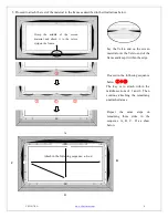
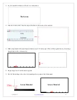
Elite Screens Aeon AR100WH2 User Manual Download Page 11

V021417-EA 

www.elitescreens.com 

11 


1)


Lay the assembled frame on its back on a clean surface. 


2)


Measure 10 mm (0.40”) from the edge of the frame to the inside of the material. 


3)


Make a light mark with a pencil approximately every 8-10 inches apart. This will help guide the way to making a 

straight line for the velveteen strip. 
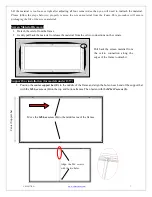


4)


Repeat steps 2 and 3 on the remaining sides 

5)


Peel off the backing on the velvet strip and align the top edge at the 10mm mark. 


The Screen 

Screen Material 

Screen Material 

10” 

10” 


10” 

Summary of Contents for Aeon AR100WH2

Page 1: ...isual appearance Assembly Video For further assistance watch our assembly and installation video at www elitescreens com video aeon assembly or scan the following QR Code For more information on the L...

Page 2: ...located on the back each horizontal frame section top bottom Note For models 180 and above insert and slide in four M6 screws two on each frame through the channel located on the back of each horizon...

Page 3: ...orizontal long frame B with the frame built in the previous steps as shown below Horizontal long frame B Vertical short frame C Horizontal Long frame B push push push push Vertical short frame C Note...

Page 4: ...uld be placed upwards Note The back side of the material has the velcro borders all around the edges 2 Carefully and gently place the assembled frame on top the screen material as shown below Make sur...

Page 5: ...by the screen material If not please loosen the velcro connection and repeat the above steps so the frame is not exposed Note The black shaded part represents the velcro on the frame That Velcro end...

Page 6: ...e and keep it within the edge Proceed in the following sequence below The key is to attach within the middle sections of 1 and 2 Then continue attaching the remaining unattached areas Repeat the same...

Page 7: ...ame 2 Gently pull back the material to release the material from the velcro connections on the corners Support bar installation for models under 135 1 Position the center support bar E in the middle o...

Page 8: ...t bar installation for models 180 200 2 Position the center support bar E and M6 hex screws G in the areas of the frame shown in fig 1 Align the hole on each end of the support bar with the M6 hex scr...

Page 9: ...der for the CineGrey 3D to perform correctly Angular Reflective material is not compatible with ultra short throw projectors Minimum lens throw ratio 1 5x image width Ambient light must not come from...

Page 10: ...size of your screen See below illustrations for a comparison of the viewing size of the before and after edge trim installation using the 100 120 16 9 diagonal models 100 comparison 120 comparison Bef...

Page 11: ...de of the material 3 Make a light mark with a pencil approximately every 8 10 inches apart This will help guide the way to making a straight line for the velveteen strip 4 Repeat steps 2 and 3 on the...

Page 12: ...where the screen is to be installed 1 Drill a hole with the proper bit size according to the wood screws included 2 Line up the wall brackets with the drilled holes on the installation location and sc...

Reviews: