background image

JA06042018 

www.eliteproav.com 


WARNING


The Screen’s 

Top Black Drop

 is already set to its maximum drop distance. There is 

NO

 extra top black drop 

in the roller. Please be aware of this as it will void the warranty. 
 
Individual modifications to this product are prohibited and will void the warranty with the manufacturer.  
Please contact Elite Screens Customer Service for any questions. 


NOTE: 

This equipment has been tested and found to comply with the limits for a Class B digital device, pursuant to 
Part 15 of the FCC Rules. 
 
These limits are designed to provide reasonable protection against harmful interference in a residential 
installation. This equipment generates and can radiate radio frequency energy and, if not installed and used 
in accordance with the instructions, may cause harmful interference to radio communications. 
 
However, there is no guarantee that the interference will not occur on a particular installation. If this 
equipment causes harmful interference to radio or television reception, which can be determined by turning 
the equipment off and on, the user is encouraged to try to correct the interference by one or more of the 
following measures. 


Reorient or relocate the receiving antenna of the device which may be causing the interference. 


Increase the separation between the screen and the device’s receiver. 


Connect the equipment into a different power outlet other than the device. 


Pre-Installation 
 

1.


Carefully unpack the screen. 

2.


Always handle the screen in a leveled position on a clean surface. 

3.


In order to protect the screen from exposure to stains, keep the screen out of contact with foreign 
particles such as dust, sawdust, and/or liquids. 

 
NOTE 

Wall screws included with this product are complementary and may not be adequate for all mounting 
surfaces. Consult with a professional installer or hardware store for proper mounting screws and anchors. 


Regardless of the mounting method, the screen should be securely supported so that the vibration or     
pulling on the viewing surface will not cause the casing to become loose or fall. The installer must insure 
that the fasteners used are of adequate strength and suitable for the installation location. 


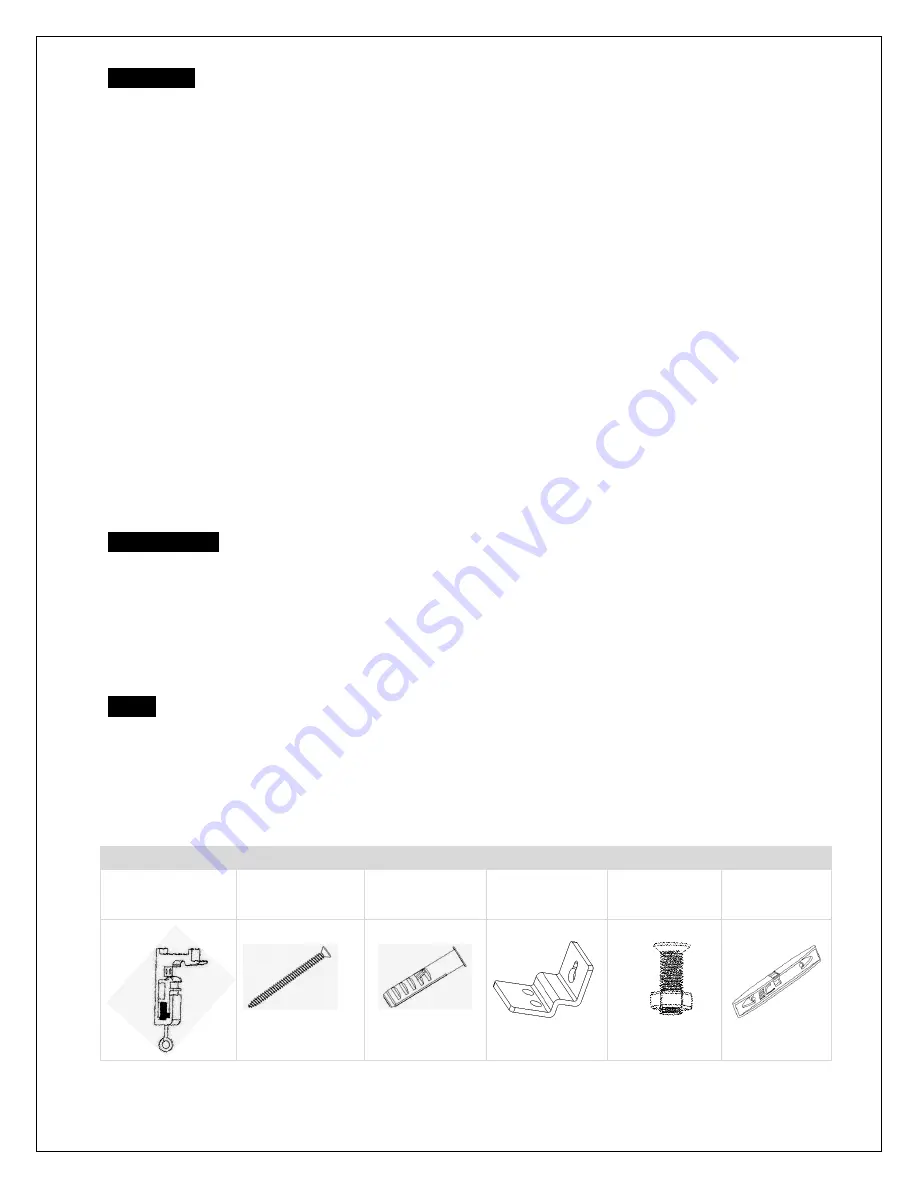
Hardware Parts List for Planate Tab-Tension Series 

A. Mounting Bracket 

x 2 pcs 

B. M4x50 Screw x 4 

pcs 

C. M12 dry-wall 

anchor x 4 pcs 

D. Suspended 

Ceiling Bracket 

Connector x 2 pcs 

E. M5x16 Screws 

& Nut x 4 pcs


F. Bubble Leveler 

x 1 pc 


Summary of Contents for Planate Tab-Tension Series

Page 1: ...lined surfaces Do not put heavy objects on the power cord and position it properly to avoid creating a trip obstacle Never overload the power cord to prevent an electric shock or fire due to a loose contact or a short circuit There are not user serviceable parts in this unit Do not attempt to disassemble this unit by yourself No one except authorized technicians can open and make repairs to this u...

Page 2: ...rect the interference by one or more of the following measures Reorient or relocate the receiving antenna of the device which may be causing the interference Increase the separation between the screen and the device s receiver Connect the equipment into a different power outlet other than the device Pre Installation 1 Carefully unpack the screen 2 Always handle the screen in a leveled position on ...

Page 3: ...re with the M4x50 Screws b Mounting Bracket Anchor Wall 3 Attach the screen to the Mounting Brackets a by inserting the top of the case to Fix Plate 1 and securing the back of the case to Fix Plate 2 Make sure the case slots are securely attached to the mounting brackets Mounting Bracket Mounting Bracket Fix Plate 1 Fix Plate 2 Mounting Bracket Case Slot 1 Case Slot 2 Screen Case Mounting bracket ...

Page 4: ...ting the top of the case to Fix Plate 1 and securing the back of the case to Fix Plate 2 Make sure the case slots are securely attached to the Mounting Bracket a Suspended Ceiling using Chains additional hardware required 1 You can also hang the screen on a ceiling by using chains not included 2 Connect the Suspended Ceiling Bracket Connector d to the Mounting Bracket a and secure with the M5x16 S...

Page 5: ...h required and not included Remove the weight bar end cap to expose the adjustment tension knob Insert your 4mm Allen Wrench to push in the adjustment tension knob turn clockwise and your screen will gain more tension Turn the Allen Wrench counter clockwise and the screen will lose tension Please note this adjustment is not necessary as the tension of the screen has been set to its factory setting...

Page 6: ... described below 6 ways to control you Planate Tab Tension 1 IR Remote Control Item A Fig 1 The Infrared functions by direct line of sight contact with a beam range of 30 feet Aim the IR remote and the circular window on the left side of the screen 2 RF Remote Control Item B The radio waves eliminate the need for a direct line of sight with a range of 100 feet 3 IR Eye Receiver Item E Fig 2 The IR...

Page 7: ...nd a wireless signal to synchronize its drop rise with the projector s power cycle Here s how to set up your Wireless 5 12 volt trigger Synchronization Instructions Step1 Connect one end of the 3 5 mm wireless 5 12 volt trigger cable to the RF remote Step 2 Connect the other 3 5 mm end of the wireless 5 12 volt trigger cable to your projector Step 3 Make sure to unplug your screen from the power o...

Reviews: