background image


Setup 


Place gel to the centre of the  

Inside (Figure 2):


-  Upper lid


-  Lighting area


-  Lid Sensor


Figure 3


   USB 2.0 port


        DC power


   VGA Our Port


Back (Figure 3):


-  DC power


-  USB 2.0 port


-  VGA port


1.


Remove all tapes used to hold items in place for shipping. 

2.


Place ZEPHYRUS

®


GelCube LED Imager

 on 

at surface. 

3.


Connect power source 

 connect AC adapter to back of unit then plug into electrical outlet. 

4.


Push power button. 

5.


Insert USB flash drive.  

6.


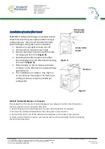
The Menu Mode icon will be displayed on the top left side of the display (

Figure 4

). 

7.


Place gel directly on the surface of the Lighting area (

Figure 5

).  

8.


Adjust the image condition and scan. 

Figure 5


Place the gel directly 


Menu mode icon 


Figure 4


Created by: VIJU

Instruction Manual ZEPHYRUS® Gel Cube Illuminator

Source: https://www.elisabeth.cz/en/product-zephyrus-gel-cube-cyanw-transilluminator.html
This file is owned by ELISABETH PHARMACON, spol. s r. o., It is issued for publication.

Version: 180220-01

Downloaded: 02.03.2020 09:17 online user

Page 5 of 16

Summary of Contents for ZEPHYRUS GelCube Illuminator Series

Page 1: ...Created by VIJU Instruction Manual ZEPHYRUS Gel Cube Illuminator Source https www elisabeth cz en product zephyrus gel cube cyanw transilluminator html This file is owned by ELISABETH PHARMACON spol...

Page 2: ...s delete scanned images 8 Installation of amber filter board 9 Menu 10 Warranty 165 Created by VIJU Instruction Manual ZEPHYRUS Gel Cube Illuminator Source https www elisabeth cz en product zephyrus g...

Page 3: ...t illumination surface CAUTION When working in a laboratory environment it is always important to properly handle all reagents and chemicals Use proper and common laboratory safety practices when work...

Page 4: ...ite Light selection switch Power Button LCD display Upper lid Figure 1 SCANNER COMPONENTS Front Figure 1 Up Down Left Right menu button USB 2 0 Port Scan button Blue Light White Light selection switch...

Page 5: ...power button 5 Insert USB flash drive 6 The Menu Mode icon will be displayed on the top left side of the display Figure 4 7 Place gel directly on the surface of the Lighting area Figure 5 8 Adjust the...

Page 6: ...te Light Panel Interface Display Panel Build in 2 7 Touch TFT LCD Output 1 USB 2 0 x2 Thermal printer and USB flash drive 2 VGA out 800x600 1024x768 General Info Power AC Adaptor 12V 4 6A Dimensions W...

Page 7: ...8 Press SCAN button green LED will ash and CAPTURING will be displayed on the screen If thermal printer had been connected with ZEPHYRUS GelCube LED Imager Printing Yes No will be displayed on the scr...

Page 8: ...to USB flash drive Scanning of the blot is now complete White Back Light mode is to scan the gel such as SDS PAGE stained with coomassie blue and further in a transparent background preservation Exami...

Page 9: ...cutting purpose by using the provided gel cutting knife Figure 8 Filter board hanging tab Small pin Amber Filter Board Figure 9 DISPLAY SCANS ON Monitor or Projector The display from the scanner can b...

Page 10: ...768 d Save Format TIF JPG BMP JPG is default setting e Quick View 1 sec 2sec 3 sec off 2sec is default setting f Slide Show Interval 2 sec 3sec 5 sec 10 sec 3sec is default setting g Power Save 1 min...

Page 11: ...criptions I Scan Mode When icon displays on top left corner of the screen the object is ready to be scanned LED Lighting Mode a When in Scan Mode press OK to get into functional option list b Press ri...

Page 12: ...normal condition 1 Color Color Invert option only occurs when in white light application Set Up Mode a When icon displays on top left corner of the screen press OK to get into functional option list...

Page 13: ...e Illuminator Source https www elisabeth cz en product zephyrus gel cube cyanw transilluminator html This file is owned by ELISABETH PHARMACON spol s r o It is issued for publication Version 180220 01...

Page 14: ...hen Scan Mode icon is highlighted press OK again to get into Play Mode c The Play Mode icon will display on top left corner of screen The captured images can then be reviewed one by one by pressing ri...

Page 15: ...X 1 2 X 2 3 X 3 and select the desired setting item Preview Mode 1 X 1 Display 1 image at a time 2 X 2 Display 4 images at a time 3 X 3 Display 9 images at a time d Press OK button to save the setting...

Page 16: ...rmacon Ltd used in the manner not described in this manual damage caused by accident neglect misuse improper service natural forces or other causes not arising from defects in original material or wor...

Reviews: