background image


- 1 - 

About this Document 

Purpose 

This document describes the features, hardware installation, network access, network 

configuration, routine maintenance, fault analysis, and troubleshooting of the Network 

Video Recorder (NVR). 

Intended Audience


This document is intended for: 


Technical support engineers 


Maintenance engineers 

Symbol Conventions 

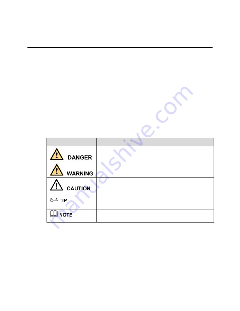
The symbols that may be found in this document are defined as follows. 

Symbol 

Description 


Alerts you to a high risk hazard that could, if not avoided, 

result in serious injury or death. 


Alerts you to a medium or low risk hazard that could, if 

not avoided, result in moderate or minor injury. 


Alerts you to a potentially hazardous situation that could, 

if not avoided, result in equipment damage, data loss, 

performance deterioration, or unanticipated results. 


Provides a tip that may help you solve a problem or save 

time. 


Provides additional information to emphasize or 

supplement important points in the main text. 


Important Statement


Users are required to enable and maintain the lawful interception (LI) interfaces of 

video surveillance products in strict compliance with relevant laws and regulations. 

Installation of surveillance devices in an office area by an enterprise or individual to 

monitor employee behavior and working efficiency outside the permitted scope of the 

local law and use of video surveillance devices for eavesdropping of illegal purposes 

constitute behaviors of unlawful interception 
.

Summary of Contents for ELI-SIP2-NVR32

Page 1: ...jury Alerts you to a potentially hazardous situation that could if not avoided result in equipment damage data loss performance deterioration or unanticipated results Provides a tip that may help you...

Page 2: ...recommended 7 3 2 Days of recorded 7 3 3 Installation 8 4 Basic operation 10 4 1 Front panel description 10 4 2 Rear panel description 11 4 3 Startup 12 4 4 Shutdown 13 4 5 Login 13 5 Quick setup 15 6...

Page 3: ...o support common browsers real time monitoring and playback Video Ability to decode Support H 264 High profile Level5 0 decode Support resolution up to 5 megapixel Real time video Single screen 5 mega...

Page 4: ...NTP others Environment temperature 10 50 Environment humidity 5 90 power supply AC110 220V 47 63HZ Maximum consumed power is 200W consumption Low power design Maximum motherboard power consumption 15w...

Page 5: ...equipment and this network is dedicated to the NVR and network cameras audio and video transmission Dedicated camera network must be connected with the NVR LAN2 and ensure that the LAN2 camera networ...

Page 6: ...be free to organize just need to ensure communication between the NVR and network camera is smooth In the use of the network LAN2 needs to turn off the camera dedicated network Open network the need...

Page 7: ...recommended Given the current market of different brands the uneven quality of the different models of hard recommended to use Seagate or Western Digital brands which are designed for security server...

Page 8: ...te recording days Hard drive capacity Video stream cameras Days recorded 4 4TB D1 1 5Mbps 32 30 days 4 4TB 720p 3Mbps 32 15 days 4 4TB 1080p 4 5Mbps 32 10 days 3 3 Installation The hard specific insta...

Page 9: ...Step 2 Hard drive inset to the PCB SATA interface Step 3 Fixed hard drive with 4 screws Repeat the step2 step3 untill all the hard drive are installed and then cover the upper cover fix the screw s E...

Page 10: ...4 1 4 hard drive work indicating lamp blue Long light when it s alive the blue light flashes when it reading and writing data 4 SYS NVR running indicator lamp red long light when it is behaving normal...

Page 11: ...arm input channel switch value RS485 1 channel RS485 5 Audio input Connect microphone linear audio 6 Audio output Linear audio output 7 RESET button Keep click the button more than 5 seconds to restor...

Page 12: ...he front panel to start the NVR the NVR conducts a self test and then display the result on the screen When an abnormality is detected and the self test screen stays on choose to continue or shut down...

Page 13: ...he PWR button on the front panel for over 3s The NVR is closed successfully when the power indicator on the front panel changes from steady on to flashing in red To shut down the NVR after logging in...

Page 14: ...e case sensitive Change the password after logging in to the NVR for the first time When a user enters incorrect passwords three times within an hour during login the account is locked For how to unlo...

Page 15: ...arch and video configuration of the NVR For the cameras added to the NVR the quick setup functions cover the network configuration code stream configuration and motion detection configuration of the c...

Page 16: ...ion status and speed are displayed in real time Network interface 2 of the NVR supports the camera dedicated network function enabled by default A camera dedicated network is a network where only webc...

Page 17: ...d total space of hard disks Section 4 camera quantity alarm The NVR searches for webcams in the network automatically when the camera dedicated network function is enabled When the number of webcams d...

Page 18: ...nd click Ok Section 5 searching and deleting cameras When the camera dedicated network function is not enabled click Search Camera to search for webcams manually The Camera Search interface appears as...

Page 19: ...he account and click Section 7 camera setup This section displays the statuses of webcams and provides setting of the names IP addresses record policies code streams and motion detection of webcams Th...

Page 20: ...alog box Set a motion detection alarm 1 Click the motion detection information to be modified The Motion Alarm dialog box appears 2 Set the deployment time and detection zone if the motion detection a...

Page 21: ...own in Figure 6 1 Figure 6 1 Live Video interface On the Live Video interface drag a camera in the Cameras pane on the left to the live channel and perform the following operations Live video playing...

Page 22: ...yback Alarm Search and Quick Setup Click each one to enter the corresponding operation interface Click to view the hard disk information of the NVR Click to enter the record backup interface Click to...

Page 23: ...he ones supported by the video device from the Stream option in the shortcut menu Code stream information is displayed at the bottom of the video pane Automatic full screen Click and choose whether to...

Page 24: ...PTZ control interface To exit the PTZ control menu click on the PTZ control interface Quick operation on the Live Video interface Right click and the Live Video menu appears shown in Figure 6 3 where...

Page 25: ...hard disks as shown in Figure 7 1 Figure 7 1 Local video playback Take the following steps to play a video Step 1 Select a camera Click a camera in the Cameras pane A selected camera is marked with A...

Page 26: ...eos are in green Enter a time point in the Focus time field and click Then the video corresponding to the specified time is played provides the time options of 15 minutes 30 minutes 1 hour 4 hours 8 h...

Page 27: ...vailable backup storage devices The NVR supports two types of backup storage device that is network storage device NAS and USB storage device USB flash drive or mobile hard disk Network storage device...

Page 28: ...isk to the USB interface on the front panel 6 The NVR detects and displays the USB storage device automatically 7 Right click the USB flash drive and choose Popup or Format to perform the correspondin...

Page 29: ...op the selection or click Cancel to unselect the selected video segment 4 Click Backup to back up the video Method 2 Click Backup on the Alarm Search interface when an alarm video is played Step 4 Vie...

Page 30: ...ocation offset You can be processed in accordance with the following methods Method automatically adjust the display function Method In the login screen select the adjustment enter the display adjustm...

Reviews: