background image

Project 19

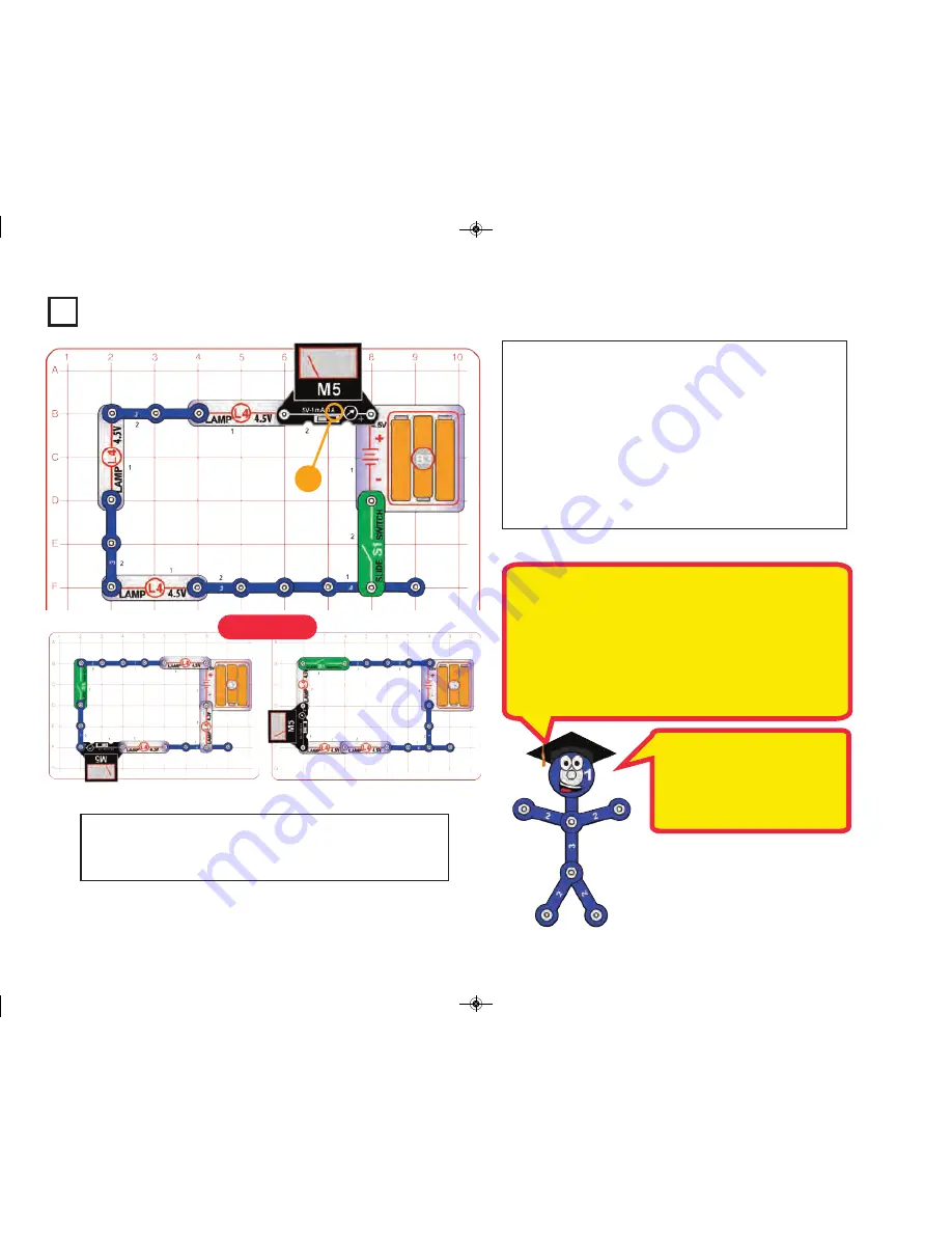
Series Swapping

Build the main circuit and set the meter (M5) on the 1A setting.

Turn on the slide switch (S1); the lamps (L4) light dimly and the

meter (M5) measures the current through the circuit. 
Now swap the positions of any of the lamps, 3-snap wires, the

slide switch and the meter (the meter should always be placed

so it hangs out of the circuit). Read the current on the meter; does

it read the same for each arrangement? 
When you turn on the switch, does the meter measure a higher

current initially than it does after a few seconds? Why?   

Note:

Your M5 meter is a simple meter.  It may read zero on this

scale even though a small current is flowing.

1A

Examples

In the first moment after you press

the switch, the meter will show a

higher “surge” current.  Light bulbs

have  less  resistance  when  you

first turn them on, then increase

resistance as they get bright.

The order of parts connected in series or in parallel does not matter -

what matters is how combinations of these sub-circuits are arranged

together.  
The choice of whether to use a series or parallel configuration in a cir-

cuit depends on the application, but will usually be obvious. For ex-

ample the overhead lights in the rooms of your home are all connected

in parallel so that you can have lights on in some rooms and off in oth-

ers, but within each room the light and switch are connected in series

so the switch can control the light.

Give some examples of series circuits in your home. 

-29-

SC_STEM1_manual_PRINT.qxp_Layout 1  7/13/17  4:42 PM  Page 30

Summary of Contents for SCSTEM1

Page 1: ...shall be reproduced by 753136 any means electronic photocopying or otherwise without written permission from the publisher U S Patents 7 144 255 7 273 377 patents pending Instruction Manual Projects 1...

Page 2: ...able and safe the instructions should enable supervising adults to establish the experiment s suitability for the child Make sure your child reads and follows all of the relevant instructions and saf...

Page 3: ...Meter 6SCM5 r 1 Battery Holder uses 3 1 5V type AA not included 6SCB3 r 1 Magnet 6SCMAG r 1 Base Grid 11 0 x 7 7 6SCBG r 1 Nut Snap 6SCNS r 1 Compass 6SCCOM r 1 Two Spring Socket 6SCPY1 r 1 White LED...

Page 4: ...installing a battery be sure the spring is compressed straight back and not bent up down or to one side A large clear plastic base grid is included with this kit to help keep the circuit blocks prope...

Page 5: ...d up The only prerequisite is basic reading skills It should take about 6 hours to do this entire book or about 2 hours to read the Introduction to Electricity page 9 and do just the educational summa...

Page 6: ...pushes water through pipes This voltage is much lower and much safer than that used in your house wiring Using more batteries increases the pres sure therefore more electricity flows The funny markin...

Page 7: ...asures voltage when connected in parallel to a circuit and measures the current when connected in series in a circuit This meter has one voltage scale 5V and two current scales 1mA and 1A These use th...

Page 8: ...agnet Sym bol with Rod Inside Grommet OTHER PARTS The magnet is an ordinary magnet like those in your home The compass is a standard compass The red needle will point toward the strongest magnetic fie...

Page 9: ...be closed or opened It contains a coil that generates a magnetic field when current flows through it The magnetic field attracts an iron arma ture which switches the contacts See project 69 for furth...

Page 10: ...represents how much it resists the elec trical pressure voltage and limits the flow of electric current The relationship is Voltage Current x Resistance When the resistance increases less current flo...

Page 11: ...ER touch the motor when it is spinning at high speed For all of the projects given in this book the parts may be arranged in different ways without changing the circuit For example the order of parts...

Page 12: ...wool to scrape off the protective coating at each end Switcher S6 Build this mini circuit With the switch in the middle position the motor M1 should be off in the top position the motor should spin c...

Page 13: ...ies 42 Propellor and Fan Motor direction 46 43 Motor Lights 47 44 Slow Motor Lights 47 Magnetism Electromagnetism 45 Compass 46 46 Magnetic Fields 47 47 Electronic Magnet 48 48 Electromagnet Magnetic...

Page 14: ...ll speed New alkaline batteries work best WARNING Moving parts Do not touch the fan or motor during operation WARNING Do not lean over the motor The air is being blown down through the blade and the m...

Page 15: ...ble the build your own electromagnet as per the instructions on page 5 or you can assemble it later and replace the 2 spring socket 1 with a 3 snap wire Set the switcher S6 to either side to light the...

Page 16: ...Storms Laboratory NSSL via pingnews Why do you often see lightning before you hear it It is because light trav els faster than sound Electrons Nucleus This diagram shows the structure of an atom excep...

Page 17: ...he air is dry How will this change if you wet your hair Try it Take a piece of newspa per or other thin paper and rub it vigorously with a sweater or pencil It will stick to a wall Cut the paper into...

Page 18: ...n a pipe 5 The slide switch S1 controls the electricity by turn ing it on or off just like a light switch on the wall of your home A switch controls electricity like a faucet controls water 6 The base...

Page 19: ...m s law What do you think their resistance will be 5V Measurements from this circuit and the project 5 circuit can be used to measure the lamp resistance using Ohm s Law 1 Measure the voltage using th...

Page 20: ...is also called the closed position Similarly the off position is also called the open po sition This is because the symbol for a slide switch is similar to the symbol for a door in an architect s dra...

Page 21: ...s 1A setting so there is nothing in the circuit to limit the current When you push the press switch the high current 1A activates a safety fuse in the battery holder B3 after a few seconds which lower...

Page 22: ...These materials are called conductors Conductors have electrons that are loosely held to the nucleus and can move easily Other materials such as paper air and plastic have very high resistance to elec...

Page 23: ...ater has relatively high resistance and a high reading means the water has relatively low resistance Which gave a higher reading on the meter long narrow shapes or short wide shapes You can use Ohm s...

Page 24: ...Power Voltage x Current Voltage Current Resistance WARNING Moving parts Do not touch the fan during operation WARNING Do not lean over the motor 1A Project 13 1A Build the circuit set the meter M5 to...

Page 25: ...hem in a circuit The advantage of it is that wiring them together is simple The disadvantage is that if one lamp breaks all three will be off How would the current change if you replaced one of the la...

Page 26: ...the flow of electricity Placing resistances in se ries increases the total resistance Advanced users can compute the total resistance as follows Rseries R1 R2 R3 The current is the same through all t...

Page 27: ...he voltage pushes the current with equal force because all are 4 5V down each path Most of the lights in your house are connected in parallel so if one bulb burns out then the others are not affected...

Page 28: ...r cell phone allow you to reverse the chemical reaction using an other electric source 5V Connecting parts in parallel is another way of arranging them in a circuit The advantage of it is that if one...

Page 29: ...cation C Measure the voltage at each location is it the same Part C swap the locations of the meter and lamp Does the meter still measure the same voltage This circuit shows that rearranging parts tha...

Page 30: ...xamples In the first moment after you press the switch the meter will show a higher surge current Light bulbs have less resistance when you first turn them on then increase resistance as they get brig...

Page 31: ...hey are used up In Part A the battery holder B3 has three 1 5V type AA batteries in series so the battery voltage is about 4 5V 1 5V 1 5V 1 5V 4 5V In Part B you are measuring two 1 5V type AA batteri...

Page 32: ...the motor Project 24 Voltage Shifter With both lamps on what is the voltage measured across the top lamp With both lamps on what do you think the voltage across the bottom lamp is Swap the locations o...

Page 33: ...e divides evenly because the lamps all have the same char acteristics This is another example of how voltage divides as parts are added in series The lamps are acting as resistors because they limit t...

Page 34: ...decreases as parts are added in series If more than one lamp is on the voltage from the batteries is split among them and less current will flow through the circuit In theory the current with one lam...

Page 35: ...rrentLampD Are the currents through circuit branches B C and D the same or different Add up the currents through circuit branches B C and D How does the total compare to the main circuit current part...

Page 36: ...tches connected in series or in parallel Give an example of an AND circuit in your home If switch S9 switch S1 AND switch S2 are on then the lamp will be on Engineers refer to this switching combinati...

Page 37: ...eats up the filament which gets so hot that it glows The left bulbs get less current than the top one so they take longer to heat up and don t get as hot barely getting hot enough to light their filam...

Page 38: ...of the lamps Find a fluorescent or LED bulb and feel the heat coming off it you won t feel much Find an incan descent lamp THAT HAS BEEN OFF FOR A WHILE and turn it on Feel the heat it produces it soo...

Page 39: ...is used to reverse the battery connections from snap A D to snaps B C which reverses the voltage across the motor and lamp In the top position battery is connected to snap B and in the bottom positio...

Page 40: ...e the fan on the motor Turn on the slide switch and set the switcher to the left so both switches are on and push the press switch The motor will not spin Now turn off the slide switch and set the swi...

Page 41: ...fan to those with the fan WARNING Moving parts Do not touch the fan during operation WARNING Do not lean over the motor 5V Project 36 3 Speed Motor with Fan Build the circuit set the switcher S6 to t...

Page 42: ...TOUCH THE MOTOR WHILE IT SPINS Next place the fan on the motor and push the press switch again the lamps stay bright as the fan speeds up The voltage from the batteries B3 pushes an electric current t...

Page 43: ...oss the battery holder as shown With all the switches off the meter measures the battery volt age Turn on the switches to light the lights and spin the motor compar ing how much the voltage changes fo...

Page 44: ...ce that the voltage is much lower then the nor mal 4 5V the motor and lamps are overloading the batteries B3 so the voltage drops Part B Turn off the circuit remove the motor and lamps then turn the c...

Page 45: ...n it is at full speed How does electricity turn the shaft in the motor The answer is magnetism The motor is the opposite of an electromagnet Moving a magnet near a coil of wire can make a current flow...

Page 46: ...43 Motor Lights 5V The electromagnet M3 has a lot more resistance than the lamps L4 Modify the preceding circuit to be this one Keep the meter M5 on the 5V scale Turn on the slide switch S1 then push...

Page 47: ...ctrodes the iron core rod and the thin bar Decide which of these you think the magnet will pick up then try it and see if you were right Do the same for other ma terials in your home The physical prop...

Page 48: ...and negative terminals of a battery Electric and magnetic fields affect each other If you place a magnet next to a radio your reception can be disturbed Magnet magnetic field Battery electric field Pe...

Page 49: ...s Pressing the switch turns on an electric cur rent which transforms the electromagnet from an ordinary coil of copper wire into a magnet An electronic magnet is much better than an ordinary magnet be...

Page 50: ...gs with the electromagnet The attraction is now very weak The iron core rod concentrated the magnetic ef fects of the electromagnet You can use the com pass to see that electronic field is now much we...

Page 51: ...er way Build the circuit as shown and drop the thin rod into the electromagnet M3 Push the press switch S2 several times The thin rod gets sucked into the electromagnet and can be suspended there or y...

Page 52: ...r the compass make sure it is securely snapped This circuit works best with new alkaline batteries Keep the circuit away from any iron objects Turn on the slide switch S1 and switch the switcher S6 be...

Page 53: ...bber grommet on one end of the iron core rod and wrap the red jumper wire tightly around it as shown Connect the red jumper wire to the circuit Turn on the slide switch S1 and set the switcher S6 to t...

Page 54: ...top and bottom positions and watch the compass to see how the magnetic field has changed Project 53 Build Your Own Electromagnet How does the build your own electromagnet used here compare with the w...

Page 55: ...he red jumper wire in project 52 wind the red wire on one side of the rod but it will not work as well because it has less windings You can also replace the white LED with the meter M5 on the 1mA sett...

Page 56: ...and M3 elec tromagnets because the build your own electromag net is in series with the lamps L4 The lamps limit the current through the build your own electromag net to avoid triggering the safety fus...

Page 57: ...ical motion here the spinning motor shaft to create electricity a current in a coil in the motor The meter shows how much current and voltage are pro duced by the spinning shaft with and without the...

Page 58: ...uses magnetism to make an electric current in a coil of wire Notice that this circuit used the 1mA meter setting while the preceding circuit used the 1A setting 1000 times greater You can produce a mu...

Page 59: ...prongs on the motor top Use a screwdriver to pry off the broken piece then push the new one on This circuit shows how much more current is produced when you spin the motor shaft faster Project 64 Magn...

Page 60: ...eplace the relay S3 with the lamp L4 Does the white LED flash Project 66 Reed Switch The reed switch is an electrical switch that can be controlled by a magnet It has two metal contacts close together...

Page 61: ...SNAP IT ON A 3 snap wire is placed across grid locations B1 B3 with the left side on lever 4 and the right side on level 3 sure it is securely snapped Place the nut snap on the 6 snap wire Turn on the...

Page 62: ...circuits do not affect each other and can operate at different voltages In this way a low voltage circuit can control a high voltage or high current circuit Most industrial machinery and home applianc...

Page 63: ...ent Set the meter to the 1mA setting Set the switcher S6 to the right position to turn the relay S3 on set the switcher to the left position to make the relay turn on and off continuously producing a...

Page 64: ...M1 and white LED D6 The electricity supplied to your home and school by your local electric company is not a constant voltage like that from a bat tery It averages about 120V but is constantly changi...

Page 65: ...oil from a different circuit wrapped around the same iron bar The magnetization of the iron bar would create a current in the other circuit This is a trans former which allows one circuit to create a...

Page 66: ...itch S1 Noth ing happens Now push the press switch S2 The lamp L4 comes on and stays on even after you release the press switch the circuit re members that you pushed the press switch Turn off the sli...

Page 67: ...until it is just barely above the nut snap without touching it 0 025 inches Turn on the slide switch S1 The lamp L4 should be on if off make sure the 4 snap is touching the 2 snap at F4 without being...

Page 68: ...best with new alkaline batteries Place the rubber grommet on the iron core rod and push the rod into the electromagnet until it is just barely above the nut snap without touching it 0 025 inches Turn...

Page 69: ...nto the lemon Set the meter M5 to the 1mA scale and connect the jumper wires to it then connect the other ends of the jumper wires to the snap electrodes red to copper Read the current from your lemon...

Page 70: ...st it It should have zero current Replace the water with fruit juices and see how they compare Sour tasting juices like lemon or grapefruit juice usually produce the most current Don t drink any water...

Page 71: ...the circuit as shown Set the switcher S6 to the top or bottom position to pull the paper clip towards the electromagnet Attract and release the paper clip using the switcher top and bottom positions...

Page 72: ..._ _ R _ S T _ U _ V _ W _ _ X _ _ Y _ _ _ Z _ _ Period _ _ _ Comma _ _ _ _ Question _ _ 1 _ _ _ _ 2 _ _ _ 3 _ _ 4 _ 5 6 _ 7 _ _ 8 _ _ _ 9 _ _ _ _ 0 _ _ _ _ _ MORSE CODE Project 85 Morse Code This sim...

Page 73: ...s stretched to make a complete circle Part C Place the circuit under a fluorescent light with a T12 bulb 1 5 diameter that runs on normal house current and spin the disc slowly As the speed changes yo...

Page 74: ...s the marker on the paper to form rings To make spiral drawings release the press switch and as the motor approaches a slow speed move the marker from the inside outward quickly Change the colors ofte...

Page 75: ...ent select how they work when the electricity is reversed LED A 1 direction only B effects unchanged C effects reversed Lamp A 1 direction only B effects unchanged C effects reversed Motor A 1 directi...

Page 76: ...ght the lamps to the right to spin the motor fan or the middle to do neither 1A Project 90 Electromagnetic Controlled Switch Build the circuit place the iron core rod in the electromagnet M3 and turn...

Page 77: ...he middle position to turn off the fan The compass is attached to the magnet push the press switch S2 to make the compass be attracted to the electromagnet M3 1A WARNING Moving parts Do not touch the...

Page 78: ...SE 25 The current through an LED is always proportional to the voltage across it TRUE or FALSE 26 Connecting several batteries in series re duces the total voltage TRUE or FALSE 27 Connecting several...

Page 79: ...y change it up with the bi color LED and get the party started with the colorful disco ball Clear and concise col orful illustrated manual includes explanations for different snap modules and concepts...

Page 80: ...damaged DO NOT RETURN TO RETAILER Call toll free 800 533 2441 or e mail us at help elenco com Customer Service 150 Carpenter Ave Wheeling IL 60090 U S A Note A complete parts list is on page 2 in this...

Reviews: