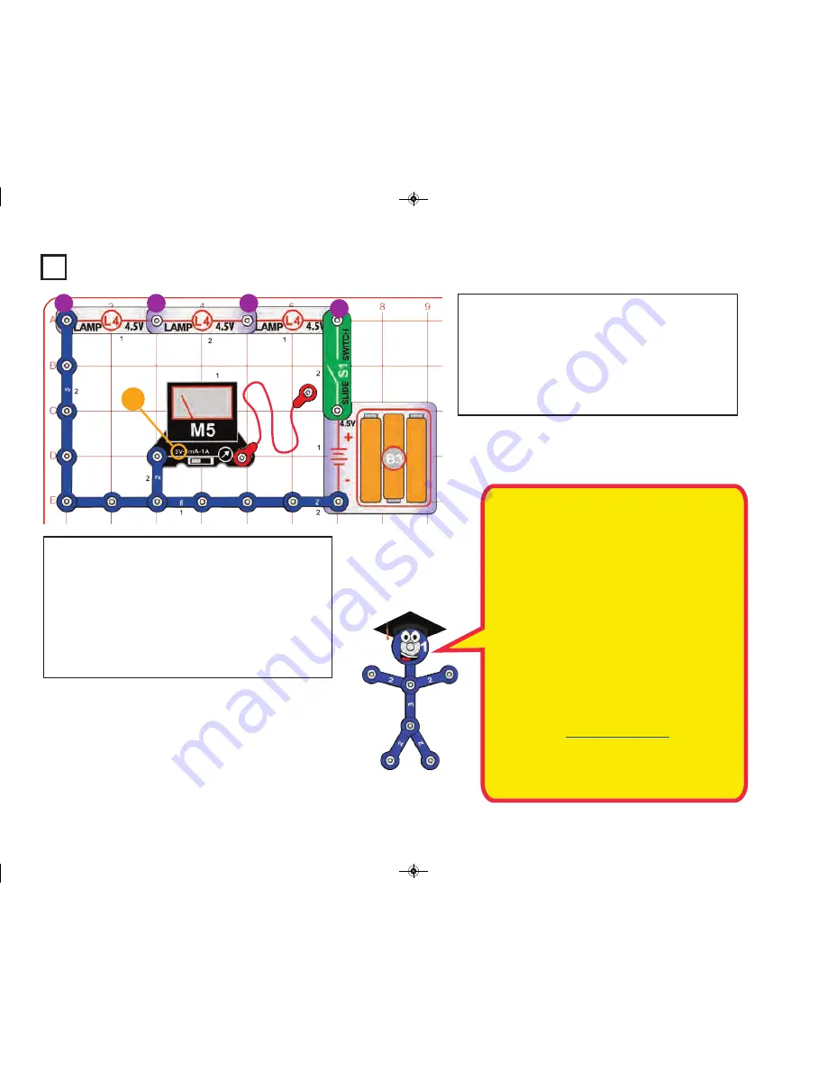
Project 15
Series Circuit - Voltage
This circuit is similar to the preceding one, but measures
the voltage instead of the current. Build the circuit, set the
meter to the 5V setting, and turn on the slide switch (S1).
The three lamps (L4) are dimly lit. Snap the loose end of
the red jumper wire to points A, B, C, or D to measure the
voltage at that point using the meter.
You can also connect the red jumper anywhere in the circuit
to measure the voltage there.
This circuit shows how the total voltage from the bat-
teries gets divided among the components in the cir-
cuit, which are resisting the flow of electricity.
In this circuit the lamps are the resistances which are
limiting the flow of electricity. Placing resistances in se-
ries increases the total resistance. Advanced users
can compute the total resistance as follows:
R
series
= R1 + R2 + R3 + . . .
The current is the same through all the resistances in
a series circuit. Ohm’s Law says that Voltage equals
Current times Resistance, so the highest resistances
in a series circuit will have the largest voltage drop
across them. Equal resistances will have the same
voltage drop. In other words:
Voltage =
(across one resistor)
Resistance
(of that resistor)
Resistance
(total of resistors in the circuit)
x Voltage
(total applied to the
series circuit)
5V
A
B
C
D
How would the voltage change if you replaced one of the
lamps with a 3-snap wire? (Try it.)
How would the voltage change if you replaced one of the
lamps with the white LED (D6, “+” on the right)? (Try it.)
-25-
SC_STEM1_manual_PRINT.qxp_Layout 1 7/13/17 4:42 PM Page 26


