-4-
ASSEMBLY INSTRUCTIONS
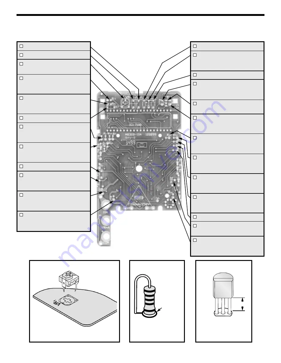
Identify and install the following parts as shown in Figure 4-1. After soldering each part, mark a check in the
box provided. Be sure that solder has not bridged to an adjacent pad.
Figure A
Figure B
Stand resistor on end as
shown with the body
inside the white circle
C3 - .1
µ
F (104) Mylar Small
C2 - .1
µ
F (104) Mylar Small
VR1 - 200
Ω
(201) Potentiometer
(see Figure A)
R13 - 900
Ω
1% 1/4W Resistor
(white-black-black-black-brown)
(see Figure B)
R15 - 180k
Ω
5% 1/4W Resistor
(brown-gray-yellow-gold)
(see Figure B)
C1 - 100pF (101) Discap
R26 - 100k
Ω
5% 1/4W Resistor
(brown-black-yellow-gold)
(see Figure B)
R16 - 100k
Ω
5% 1/4W Resistor
(brown-black-yellow-gold)
(see Figure B)
C6 - .1
µ
F (104) Mylar Small
R8 - .99
Ω
.5% 1/4W Resistor
(black-white-white-silver-green)
(Standard Location)
R* - 100
Ω
5% 1/4W Resistor
(brown-black-brown-gold)
(see Figure B)
R21 - 220k
Ω
5% 1/4W Resistor
(red-red-yellow-gold)
(see Figure B)
Figure C
Mount the transistor with
the flat side in the same
direction marked on the
PC board.
Mount the potentiometer to the PC board
as shown.
1/8”
C4 - .1
µ
F (104) Mylar Small
R14 - 300k
Ω
5% 1/4W Resistor
(orange-black-yellow-gold)
(see Figure B)
C5 - .1
µ
F (104) Mylar Large
R23 - 510k
Ω
5% 1/4W Resistor
(green-brown-yellow-gold)
(see Figure B)
Q2 - 9014 Transistor
(see Figure C)
R25 - 470k
Ω
5% 1/4W Resistor
(yellow-violet-yellow-gold)
(see Figure B)
R20 - 2.2M
Ω
5% 1/4W Resistor
(red-red-green-gold)
(see Figure B)
R24 - 820k
Ω
5% 1/4W Resistor
(gray-red-yellow-gold)
(see Figure B)
R19 - 2.2M
Ω
5% 1/4W Resistor
(red-red-green-gold)
(see Figure B)
R9 - 10
Ω
5% 1/4W Resistor
(brown-black-black-gold)
(see Figure B)
R18 - 2k
Ω
PTC1
D1 - 1N4007 Diode
(see Figure E)
R22 - 220k
Ω
5% 1/4W Resistor
(red-red-yellow-gold)
(see Figure B)
White Circle


