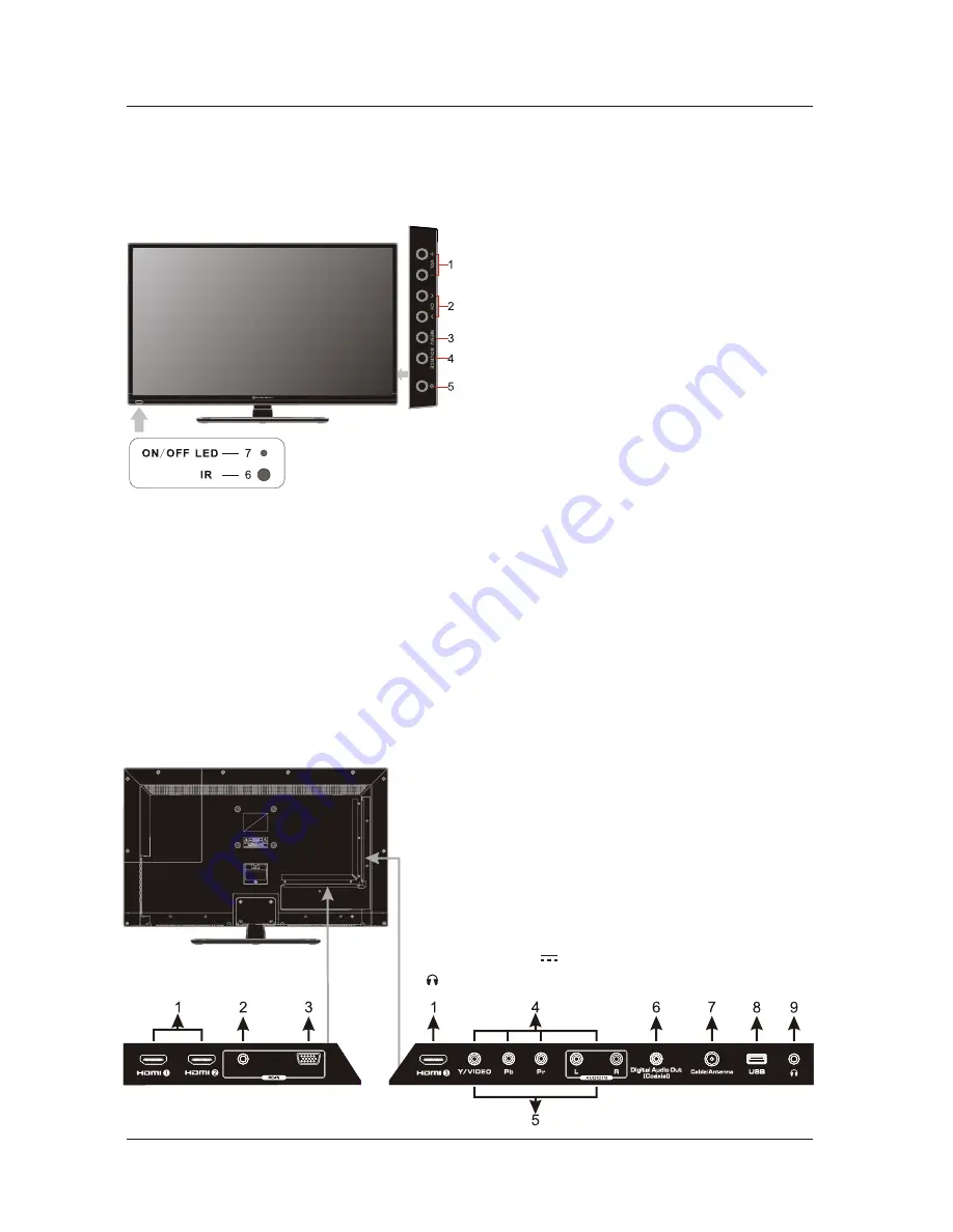
background image

Front View

5. FRONT

/

BACK CONNECTIONS OF TV

Back View and Control Connections

1. Press

 “

VOL+

 or 

VOL-

 to increase or decrease

    the volume.

2. Press

 “

CH

   ” 

or 

CH

   ” 

to scan through channels.

3.


Press 

MENU

” 

to bring up the main menu on 

    the screen. 

4. Press

 “SOURCE” 

to select the input source.

5. Press

 “

POWER


button to turn the


TV on or off.

6. REMOTE SENSOR: Infrared sensor for the 
    remote control.

7. POWER INDICATOR: 

 red


in standby


mode

.


 blue


when your TV is turned on.

Shows

Shows

FRONT

/

BACK CONNECTIONS OF TV

7

5.  VIDEO

/

AUDIO

(

L

/

R

)

: Connect the Video

/

Audio output 


jack of DVD or


VCR

.

4.  YPbPr

/

AUDIO

(

L

/

R

)

: Connect the YPbPr 

/

Audio


output jack 


of DVD or VCR.

7.  Cable/Antenna: RF input that connects to your cable or 


VHF/UHF antenna.

3

.

  VGA

(

PC

)

: Connects to a personal computer's video 


output connector.

2.  

AUDIO

(

PC

)

Connects to a personal computer's audio 


output connector.

6.  Digital Audio Out (Coaxial): Connects to the coaxial audio input 


of your digital stereo equipment.

<

>

1.  HDMI1

/

HDMI2

/

HDMI3: HDMI (High-Definition Multimedia 


Interface) provides an uncompressed, all-digital audio/


video interface between this TV and any HDMI-equipped 


A/V equipment. HDMI supports enhanced, or high-


definition video, plus digital audio.


Output


power


5V


0

.

5A

.

PC

-

AUDIO

VGA

8.  USB: Connect


to


the


external


drive

.

9.  


: Connect


to


the


headphone

.

Summary of Contents for ELEFT326

Page 1: ...32 HD Digital LED TV ELEFT326...

Page 2: ......

Page 3: ...tup 14 12 TABLE OF CONTENTS 1 IMPORTANT INFORMATION 11 SPECIFICATIONS 2 PREFACE 10 TROUBLESHOOTING 3 SAFETY PRECAUTIONS 5 FRONT BACK CONNECTIONS OF TV 7 REMOTE CONTROL 6 TV INSTALLATION DRAWINGS 4 IN...

Page 4: ...this device may not cause harmful interference and 2 this device must accept any interference received including interference that may cause undesired operation Reorient or relocate the receiving ante...

Page 5: ...ot expose this apparatus to rain or moisture 17 Mains plug or appliance coupler is used as the disconnect device shall be readily operable WARNING The battery battery or batteries or battery pack shal...

Page 6: ...he model 3 SAFETY PRECAUTIONS Power cord and cables must be properly placed and protected to prevent people from stepping on them and causing the TV to fall Minimum distances 10cm 20cm 10cm 5cm Put th...

Page 7: ...an the TV Only clean the TV with a soft and dry cloth In case of troubleshooting do not use spare parts other than those suggested by the manufacturer Using inadequate spare parts can lead to electric...

Page 8: ...Digital LED TV ELEFT326 6 4 IN THE CARTON Remote Control 1 5V 1 5V AAA Batteries LED TV SET USER S MANUAL IN THE CARTON Quick Start Guide Warranty Card Remote Control Guide OK Products Technical Assi...

Page 9: ...t jack of DVD or VCR 4 YPbPr AUDIO L R Connect the YPbPr Audio output jack of DVD or VCR 7 Cable Antenna RF input that connects to your cable or VHF UHF antenna 3 VGA PC Connects to a personal compute...

Page 10: ...allation and connection After installation insert the 75 ohm antenna plug into the antenna jack as shown Antenna Connection 75 OHM ANTENNA PLUG POWER PLUG OF ANTENNA AMPLIFIER OUTDOOR ANTENNA AMPLIFIE...

Page 11: ...left is white and Audio right is red Select component input source using the SOURCE button on the remote control Connect the VIDEO and AUDIO output jack of the DVD or VCR to the VIDEO jacks on the se...

Page 12: ...AUDIO jack on the set Select the VGA input source using the SOURCE button on the remote control COAXIAL Connection TV INSTALL TION DRAWINGS A COAX Cable The audio amplifier back Audio Amplifier TV Bac...

Page 13: ...move the screws holding the base to the base bracket and lift the base away do not remove the base mounting brackets Mount the VESA bracket using 4 x M5x10 isometric threaded screws not supplied Do no...

Page 14: ...12 REMOTE CONTROL 7 REMOTE CONTROL Remote Control Instructions Note The picture of remote controller is only for reference and is subject to the real one 21 22 23 24 25 26 27 28 29 30 31 32...

Page 15: ...or DTV input Turn the LED TV ON or OFF Press to mute the sound Press again or press Vol to un mute the TV P MODE Press repeatedly to cycle through the available video picture modes S MODE Press to cyc...

Page 16: ...gs 3 Replace the battery cover To prevent battery leakage which may result in bodily injury or damage to the remote 1 Install all batteries correctly and as marked on the remote control 2 Do not mix o...

Page 17: ...uage When you are satisfied with your choice press button to select the Auto Scan press button to search channel Volume Adjustment 1 Press VOL to adjust the volume 2 If you want to switch the sound of...

Page 18: ...he CH CH at the side of the panel or CH CH on the remote control to scan through channels 2 Enter the channel number with the 0 9 remote keys then press OK to confirm 16 MENU OPERATION Selecting Input...

Page 19: ...d then use to move the PICTURE menu press or OK to enter see picture below NOTE Adjust the parameters of the picture the Picture Mode is automatically converted to User Mode Picture Mode Select the ty...

Page 20: ...the MENU at the side of the panel or on the remote control and then use to move the TIME menu press or OK to enter see picture below Sleep Timer MENU 18 MENU OPERATION Setup Menu Options Press the MEN...

Page 21: ...ic selection among CC1 CC2 CC3 CC4 Text1 Text2 Text3 and Text4 Press and then use to select the advanced selection among Service1 Service2 Service3 Service4 Service5 or Service6 Press and then use to...

Page 22: ...w 4 digital password and input it again to confirm System Lock Allows you to turn on or off the system lock If you turn off the system lock then the following items US Canada RRT Setting and Reset RRT...

Page 23: ...n Motion Picture Association of America MPAA Rating System TV Parental Guideline Rating System MENU 21 MENU OPERATION Channel Menu Options Air Cable Allows you to select antenna between Air and Cable...

Page 24: ...nnel Name Channel Name Add Delete Add Delete 11 0 11 0 Press OK change Press OK change Favorite Allows you to add these channels which you desired as the favorite channels Use button to highlight the...

Page 25: ...e Input Source to USB Photo Menu Press button to select USB in Input Source then press OK button to enter Press button to select Photo in the main menu Press button to select drive disk you want to wa...

Page 26: ...lt from a lighting signal from car motor neon light and other electrical devices or appliances May be the result of an electrical wave disturb from other TV Computer and Game machine or Radio The cabl...

Page 27: ...AC 100 240V 60Hz SCART IN Power Consumption Input Power 65W USB COAXIAL OUT VGA PC AUDIO IN DVD TV Dimensions This manual is only for your reference any change to the design and specification will not...

Page 28: ......

Reviews: