Page 27
EA Elektro-Automatik GmbH
Helmholtzstr. 31-37 • 41747 Viersen
Germany
Fon: +49 2162 / 3785-0
Fax: +49 2162 / 16230
www.elektroautomatik.de
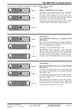
PSI 9000 WR 3U Slave Series
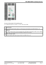
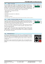
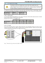
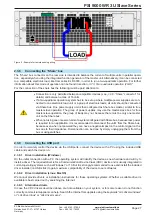
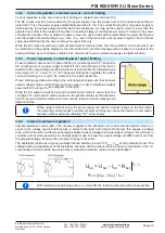
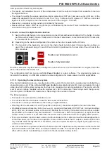
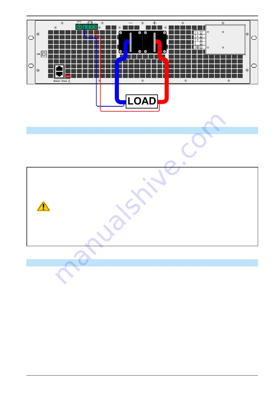
Figure 8 - Example for remote sensing wiring
2.3.8
Connecting the “Share” bus
The “Share” bus connector on the rear side is intended to balance the current of multiple units in parallel opera-
tion, especially when using the integrated function generator of the master unit. Alternatively, it can be connected
to a compatible electronic load, like from series ELR 9000, in order to run a two-quadrants operation. For further
information about this mode of operation can be found in section
„3.7.3. Two quadrants operation (2QO)“
.
For the connection of the share bus the following must be paid attention to:
•
Connection is only permitted between compatible devices (see
for
details) and between a max. of 16 units
•
If a two-quadrants operation system has to be set up where multiple power supplies are con-
nected to one electronic load unit or a group of electronic loads, all units should be connected
via Share bus. One power supply unit is then configured as Share bus master, similar to true
master-slave operation. The group of power supplies may use the master-slave bus for true
master-slave operation, the group of loads may not, because there must be only one master
unit on the Share bus.
•
When not using one or several units of a system configured with Share bus, because less power
is required for an application, it is recommended to disconnect the unit’s from the Share bus,
because even when not powered they can have a negative impact on the control signal on the
bus due to their impedance. Disconnection can be done by simply unplugging them from the
bus or using switches.
2.3.9 Connecting the USB port
In order to remotely control the device via the USB ports, connect the device with a PC using the included USB
cable and switch the device on.
2.3.9.1 Driver installation (Windows)
On the initial connection with a PC the operating system will identify the device as new hardware and will try to
install a driver. The required driver is for a Communications Device Class (CDC) device and is usually integrated in
current operating systems such as Windows 7 or 10. But it is strongly recommended to use and install the included
driver installer (on USB stick) to gain maximum compatibility of the device to our softwares.
2.3.9.2 Driver installation (Linux, MacOS)
We cannot provide drivers or installation instructions for these operating systems. Whether a suitable driver is
available is best carried out by searching the Internet.
2.3.9.3 Alternative drivers
In case the CDC drivers described above are not available on your system, or for some reason do not function
correctly, commercial suppliers can help. Search the Internet for suppliers using the keywords “cdc driver windows“
or “cdc driver linux“ or “cdc driver macos“.


