
Page 18
EA Elektro-Automatik GmbH
Helmholtzstr. 31-37 • 41747 Viersen
Germany
Fon: +49 2162 / 3785-0
Fax: +49 2162 / 16230
www.elektroautomatik.de
PSI 9000 WR 3U Slave Series
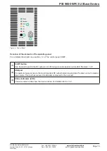
1.9.4 The control panel (HMI)
The HMI (
H
uman
M
achine
I
nterface) consists of six coloured LEDs, a pushbutton and an USB-B port.
1.9.4.1 Status indicators (LED)
The six coloured LEDs on the front indicate various statuses of the device:
LED
Colour
Indicates what when lit?
Power
orange / green
Orange = device is in boot phase or internal error occurred
Green = device is ready for operation
Remote
green
Remote control by master or any of the USB ports is active. In this situation, manual
control with button On/Off is locked.
Error
red
At least one unacknowledged device alarm is active. The LED can signalise all
alarms as listed in
CC
yellow
Constant current regulation (CC) is active. It means, if the LED is not lit it indicates
either CV, CP or CR mode. Also see
On
green
DC output is switched on
Off
red
DC output is switched off
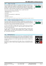
1.9.4.2 USB port
The front USB port is easier to access than the one on the rear side and intended for quick setup of DC output
related values and settings. Doing so is only necessary and possible in these two situations:
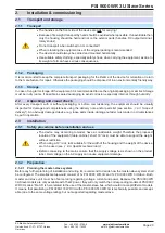
1. The PSI 9000 WR 3U Slave shall run as stand-alone device which is not controlled by a PSI 9000 WR 3U master.
2. The PSI 9000 WR 3U shall, due to the lack of a suitable PSI 9000 WR 3U master device, be the master of
other PSI 9000 WR 3U Slave devices.
Both situations are only secondary, as the primary and normal function of a PSI 9000 WR 3U Slave is to be a slave
in a master-slave system where it is assigned all required settings and values from the master.
When running any of the above listed situations following applies to the USB port:
•
Reduced instruction set for master-slave configuration, output values (U, I, P, R) and protec
-
tions (OVP, OCP, OPP). For details about the instruction set see
•
Taking over remote control in order to change the configuration is only possible while the unit
is not online with the master, which either requires to temporarily deactivate master-slave on
the master or to switch the master off
1.9.4.3
Pushbutton “On / Off”
This button can be used to switch the DC output on or off during manual control, i.e. the device is not in
remote control by a master or via any of the USB ports (LED “Remote” = off). Once pushed to switch the
DC output on, the device would regulate the output to the last values it has stored. Since all the output
related values are not displayed, operating that button has to be done with caution.
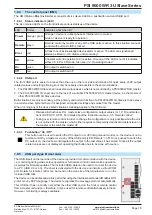
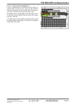
1.9.5 USB port type B (rear side)
The USB-B port on the rear side of the device is provided for communication with the device,
i.e. monitoring during master-slave operation or full remote control in stand-alone operation,
as well as for firmware updates. The included USB cable can be used to connect the device
to a PC (USB 2.0 or 3.0). The driver is delivered with the device and installs a virtual COM
port. Details for remote control can be found on the web site of the manufacturer or on the
included USB stick.
The device can be addressed via this port either using the international standard ModBus RTU
protocol or by SCPI language. The device recognises the message protocol automatically.
This USB port has no priority over either the other USB port on the front or remote control
from a master unit and can, therefore, only be used for remote control alternatively to these.
However, monitoring is always available.


