


31
Instruction Manual
PSI 800 R Series
EN
Date: 01-25-2016
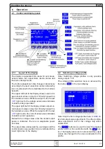
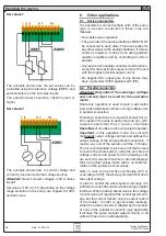
Monitoring voltage and current
The analog monitoring outputs put out 0...5V or
0...10V, depending on the voltage range selection
in the setup, which each corresponding to 0...100%
of the nominal values.
Reference is analog ground (AGND).
5.2.2 Application examples
Note: recommended cross section when wiring the
clamp pins of the analog interface: 0,1mm² (AWG26)
to 0,5mm² (AWG20).
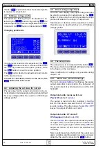
Remotely switching DC output on / off
This input can be used to switch
off
the DC power
output even without activated remote control, except
the control location was set to
local
(also see sec-
tion 3.8). In this situation the pin acts as a disabler,
preventing the DC output from being switched on
again, which would have to be done with ON/OFF
button on the panel. If the input is configured to
LOW
(see section 4.6.2), then the power output can
only be switched on again by opening the contact
or releasing the switch.
During normal remote control via analog interface,
this pin solely defines the state of the DC output.
Handling the device
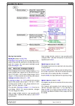
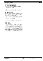
5.2.1
Pin assignment and technical specifications of the analog interface
Pin
Name
Typ
1
Description
Level
Electrical specifications
1
VSEL
AI Set value: voltage
0….10V correspond to
0….100% U
Nom
Accuracy 0.2%, U
Max
= 12V
2
CSEL
AI Set value: current
0….10V correspond to
0….100% I
Nom
Input impendance >100k
3
VREF
AO Reference voltage
10V / 5V
Accuracy < 0.1% bei I
Max
= 10mA
Short-circuit-proof against AGND
4
VMON
AO Actual value: voltage
0….10V correspond to
0….100% von U
Nom
5
CMON
AO Actual value: current
0….10V correspond to
0….100% von I
Nom
6
AGND
Reference for analogue signals
For VSEL, CSEL, CMON, VMON, VREF
7
Remote
DI Activate external controls
External = Low (U
Low
<1V),
Internal = High (U
High
>4V)
8
Rem_SB
DI Power output on/off
Off = Low (U
Low
<1V)
On = High (U
High
>4V)
9
Error
DO Various errors like
OVP, OT
Low = No error (U
Low
<1V)
High = Error (U
High
>4V)
U
Max
= 15V, I
Max
= -10mA
Quasi open collector with pull-up to Vcc
2
10
DGND
Reference for digital signals
For control and condition signals
11
CV
DO Regulation mode
Low = Voltage controlled (U
Low
<1V)
High = Current controlled (U
High
>4V)
U
Max
= 15V, I
Max
= -10mA
Quasi open collector with pull-up to Vcc
2
12
+VCC
AO Auxiliary voltage
12….16V
I
Max =
24mA
Short-circuit-proof against DGND
1)
AI = Analogue input, AO = Analogue output, DO = digital output
2)
12V...15V
U
Max
= 0…15V
I
Max
= -3mA bei 15V
Accuracy < 0.2% bei I
Max
= +2mA
Short-circuit-proof against AGND


