53
Instruction Manual
PSI 8000 3U Series
EN
Date: 05-03-2012
About the power supply
6. Handling
6.1 The display
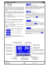
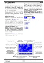
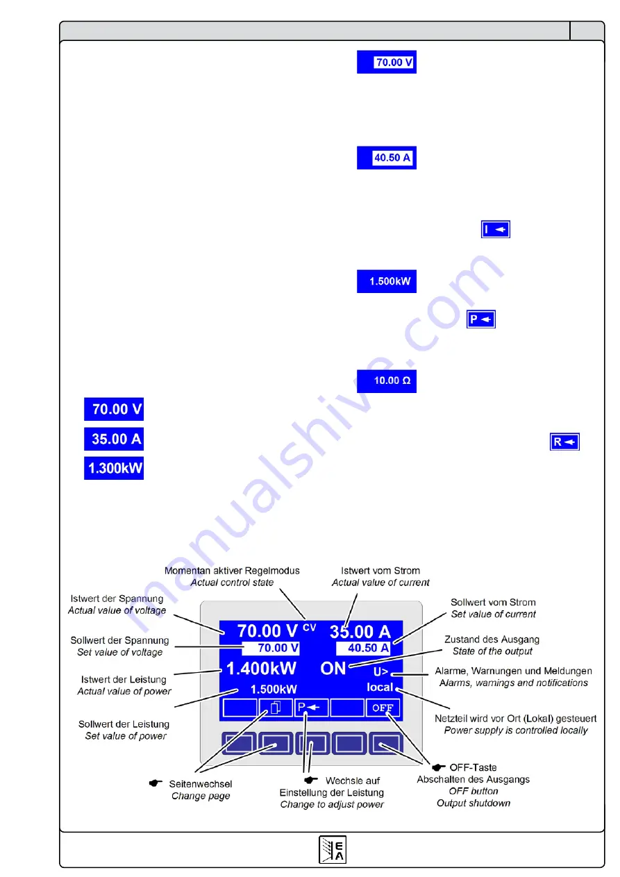
Figure 8 below shows an overview of the graphical display.
During normal operation, the display shows the actual and set
values of voltage (upper left), current (upper right) and power
(lower left). In device setup mode, it display parameters and
settings.
In case the optional „internal resistance control“ is unlocked, the
power set value might be replaced by the internal resistance
set value, depending on what is selected in the device setup.
6.2 Used symbols
In the following description the display and operating elements
are marked by different symbols.
=
Displayed only
, all elements which are only displayed
and which represent a state are marked with this symbol
=
Parameter
, changeable values are marked with this
symbol and are emphasised
=
Menu items
, selectable, lead to the next sublevel or to
the bottom level with parameters
Brackets
{…}
mark possible options or adjustment ranges for
parameters.
6.3 Short overview about the display elements
Actual value of the output voltage
Actual value of the output current
Actual value of the output power
During normal operation the actual values are displayed by
bigger numbers.
Set value of voltage
Target value of the desired output voltage (left knob). The value
is adjusted in coarse (see section 6.6 for step widths) or fine
(always rightmost digit). Switching between coarse and fine is
done with the pushbuttons on the left rotary knob.
Set value of current
Target value of the desired output current (right knob). The
value is adjusted in coarse (see section 6.6 for step widths)
or fine (always rightmost digit). Switching between coarse and
fine is done with the pushbuttons on the right rotary knob. It
might be required to push button
before the set value
is adjustable.
Set value of the power
Target value of the desired maximum output power (right knob).
In order to set the value, button
has to be pushed before.
The value is adjusted in coarse (see section 6.6 for step widths)
or fine (always rightmost digit).
Set value of internal resistance (optional)
Target value of the desired internal resistance value (right knob).
This set value replaces the power set value if the internal resi-
stance control is unlocked and U/I/R mode has been selected
in the device setup. In order to set the value, button
has
to be pushed before.
Figure 8

