Elektra Beckum 170 - 230 Amp Models Operating Instruction Download Page 10

6

Practical Hints for MIG Welding

This distance required between the torch and the workpiece is directly related to the welding current:

small current

=

small distance

high current

=

greater distance

Too little distance causes excessive wear of the contact tip and gas shroud. Too much distance will not provide
enough gas protection of the welding seam, it becomes porous.
Move the welding gun along the seam in a steady motion, always keeping the same distance between the torch
and workpiece.
Welding may be done either forehand or backhand, in a straight line or, with larger gaps, in a pendulum motion.
MIG welding is suitable for thin plate welding, as well as for welding thicker materials of up to 12 mm.
For thin plate welding we recommend the use of electrode wire of 0.6 mm diameter and a mixed shielding gas.

Welding Preparations

Attach earth clamp to work piece as close as possible to the welding seam (remove rust, paint etc. to ensure good
conducting). Set welding current and wire feed speed with welding step selector and wire feed speed regulator as
required. Make trial runs on scrap material to find correct setting.

6.1 Earth Cable

Connect earth cable plug to Earth Cable Socket on the machine's front panel. Use only genuine Elektra Beckum
parts with recommended cross sections. Structural components, beams, pipes or rails should not be used for earth
conducting, if they are not the actual workpiece. When using welding tables or jigs ensure proper conducting.

6.2 Gas Flow Setting

The correct amount of shielding gas and a steady gas flow at the welding seam are essential to provide sufficient
shielding of the weld pool. Insufficient shielding causes porous welding seams.

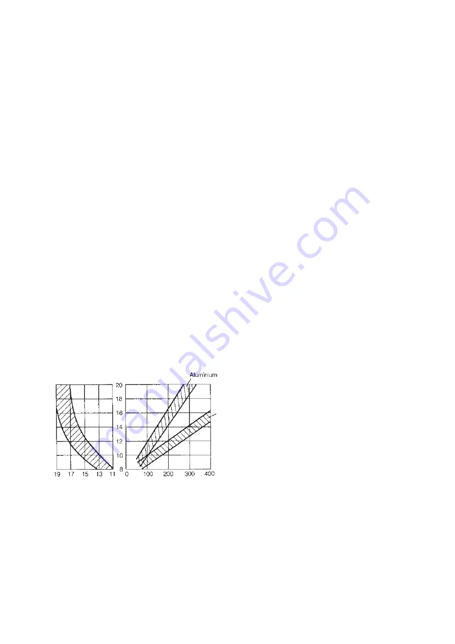
Rule of thumb to calculate the shielding gas flow rate required:

Amount of gas in ltr/min = 10 x the electrode wire diameter in mm
Example: Wire diameter 1.0 mm requires a gas flow rate of 10 ltr/min.

Diagram showing the exact gas flow rate required, accounting for different welding current settings

Gas flow rate
in ltr/min

Gas shroud

diameter in mm

Welding current in A

Steel

7

Maintenance

The contact tip and gas shroud are the parts most exposed to the radiant heat of the arc and thus are normal
wearing parts. They have to be cleaned regularly of spatters and sprayed with anti-clogging spray.
Execessive built-up of spatters can short-circuit contact tip and gas shroud, ruining both. Spatter built-up inside
the gas shroud also affects the gas flow to the welding seam.
The machine has to be checked in regular intervals for visible damages.
Dust built-up inside the machine can reduce the duty cycle considerably and may even cause a short circuit. Check
regularly and clean if necessary.
Before removing side panel be sure that machine is disconnected from power supply to prevent injury from electric
shock.

Summary of Contents for 170 - 230 Amp Models

Page 1: ...uiksaanwijzing Lasapparaat MIG MAG 170 230 D GB F NL Achtung Lesen Sie diese Anleitung vor der Installation und Inbetriebnahme aufmerksam durch Attention Carefully read through these instructions prior to installation and commissioning Attention Prière de lire attentivement la présente notice avant l installation et la mise en service Attentie Lees deze instructies voor de installatie en ingebruik...

Page 2: ...capacity 4 0 kVA 3 6 4 0 kVA Mains 50 60 Hz AC 1 230 V 1 230 2 400 V Frequency 50 60 Hz 50 60 Hz Welding steps 6 6 Wire diameter 0 6 0 8 mm 0 6 0 8 mm Weldable material 0 5 5 mm 0 5 5 mm Duty cycle 25 c 40 C 160 A 30 20 160 A 30 20 100 25 c 40 C 90 A 60A 90 A 60A Mains fuse T 16 A T 16 A Cooling F F Protection class IP 21 IP 21 Isulation class F F Welding gun assembly SB 14 2 SB 14 2 Dimensions l ...

Page 3: ...clamp wire brush and nozzle anti clogging spray delivery 2 Regulations for the Prevention of Accidents Know the applicable regulations for electric arc welding and strictly adhere to Safety Instructions Protection against electrical accidents Welding cables are to be firmly connected to ensure proper conducting capacity Mains cord and welding cables are to be protected against damages Replace dama...

Page 4: ... no load voltage a Arithmetic mean value in case of direct current b RMS value in case of alternating current c Ur V Reduced rated no load voltage in case of a voltage reducing device d Us V Switched rated no load voltage in case of an a c to d c switching device Box 10 A V to A V Range of output rated minimum and maximum welding current and their corresponding conventional load voltage Box 11 X D...

Page 5: ...etic mean value in case of direct current b RMS value in case of alternating current c Ur V Reduced rated no load voltage in case of a voltage reducing device d Us V Switched rated no load voltage in case of an a c to d c switching device Box 10 A V to A V Range of output rated minimum and maximum welding current and their corresponding conventional load voltage Box 11 X Duty cycle duty factor sym...

Page 6: ...se clamp provided Open gas cylinder valve briefly to clear any foreign matter from it than attach pressure regulator Set regulator to required gas flow rate approx 10 13 ltr min 2 5 3 GPM Caution Do not dismantle the pressure regulator for any reason It may explode when assembled incorrectly 1 Phase Machines These machines come fitted with a Schuko 2 prong plug with earth contact as standard For t...

Page 7: ...switch Earth cable socket 230 V 400 V Combi Machines Combi models come with a CEE 3 phase 5 prong plug fitted to power cord as standard and an adaptor with 1 phase plug If a 3 phase plug matching your local standard outlet has to be installed connection has to be made to 2 phases neutral and earth For 380 415 V operation connect to 2 phases zero and earth lead L1 black L2 brown earth lead yellow g...

Page 8: ...romthefeedroller by pushing the lever back For 1 0 or 1 2 mm wire the corresponding outer groove is required Place spacer washer onto drive shaft then feed roller so that the required groove size is in line with the wire intake of the central goupling For 0 6 or 0 8 mm wire the inner grooves are required Place feed roller first onto shaft followed by the spacer washer After spacer and feed roller ...

Page 9: ... A A minium electrode wire diameter of 0 8 1 0 mm is recommended Stainless Steel Welding As with aluminium as pure inert shielding gas is required Setting of the welding current as with carbon steel Prepare torch lead assembly for aluminium welding but use standard contact tip and conical gas shroud Recommended gas flow rate 8 12 ltr min To prevent a porous weld seam forehand welding is recommende...

Page 10: ...l components beams pipes or rails should not be used for earth conducting if they are not the actual workpiece When using welding tables or jigs ensure proper conducting 6 2 Gas Flow Setting The correct amount of shielding gas and a steady gas flow at the welding seam are essential to provide sufficient shielding of the weld pool Insufficient shielding causes porous welding seams Rule of thumb to ...

Page 11: ...k replace if necessary Replace Replace 2 amp time lag Wire feed speed not adjustable PCB defective Replace Not welding current with normal working wire feed Contactor faulty Step with faulty Earth cable not conducting Replace Replace Correct Arcing when gas shroud touches workpiece Short circuit between contact tip and gas shroud Clean shroud treat with anti clogging spray or nozzle dip see footno...

Page 12: ...0 212 7911 x x Power cord Combi 840 212 7938 x x Adaptor Combi 1 ph 2 ph 100 200 4956 x x Magnetic valve 805 205 2433 x x x x x Spool carrier 132 107 3880 x x x x x Wire feed motor 24 V 801 113 0047 x x x x x Feed roller Ø 30 132 515 4795 x x x x x Grooved ball bearning 710 001 0180 x x x x x Pressure spring 705 108 6532 x x x x x Spring guide 132 508 5840 x x x x x Steel liner 140 mm 132 707 1129...

Page 13: ...scription Order No 63 KZ2 adaptor block 132 707 5515 64 Liner positioner nut M10x1 132 706 4106 65 O ring 132 706 4092 66 Trigger wire connector fermale 132 706 4084 100 Contact tip ECU M6 0 6 mm 5x 090 202 7645 100 Contact tip ECU M6 0 8 mm 5x 090 202 7653 130 Gas nozzle con 3x 090 202 7742 131 Gas nozzle cyl 3x 090 202 7750 132 Gas nozzle con small 132 704 5365 133 Gas nozzle tapered 132 704 537...

Page 14: ... 132 706 4084 Pos Description Order No 100 Contact tip ECU M6 0 6 mm 5x 090 202 7645 100 Contact tip ECU M6 0 8 mm 5x 090 202 7653 100 Contact tip ECU M6 1 0 mm 5x 090 202 7669 100 Contact tip ECU M6 1 2 mm 132 705 6693 130 Gas nozzle conical 3x 090 202 7742 131 Gas nozzle cylindrical 3x 090 202 7750 132 Gas nozzle conical small 132 704 5365 133 Gas nozzle tapered 132 704 5373 134 Gas nozzle studw...

Page 15: ...mtr 132 714 4550 150 Polyamid liner 0 8 1 2 4 mtr 132 714 4541 150 Polyamid liner 0 8 1 2 5 mtr 132 714 4533 152 Guide tube polyamid liner 4 0 OD 132 704 5578 153 O ring 3 5x1 5 for guide tube 132 707 5531 Contact tip wrench not shown 132 704 5411 Pos Description Stock No Welding Torch SB 25 2 with torch leads 3 mtr 090 200 8330 with torch leads 4 mtr 090 200 8349 with torch leads 5 mtr 090 200 83...

Page 16: ...roduto está de acordo com as seguintes normas de acordo com as directrizes dos regulamentos Vi försäkrar på eget ansvar att denna produkt överensstämmer med följande standarder Enligt bestämmelserna i direktiven FIN SUOMI NO NORGE VAATIMUKSENMUKAISUUSVAKUUTUS SAMSVARSERKLÆRING Vakuutamme että tämä tuote vastaa seuraavia normeja on direktiivien määräysten mukainen Vi erklærer under eget ansvar at d...

Page 17: ...WELD D O O Ilindenska 138 1000 Skopje 389 2 363 180 389 2 364 746 MAKWELD mt net mk Magyarorszag INNOSERVICE METABO Márkaszerviz Kft 1101 Bp Köbányai út 47 b 1475 Budapest 36 12 60 67 12 36 12 60 14 23 innoservice mail datanet hu Malaysia Finetools SDN BHD No 7 Jalan 1 92C Batu 3 1 4 Jalan Cheras 56100 Kuala Lumpur 60 3 92002966 92003966 60 3 92007599 finetools pd jaring my Malta G T Imports Limit...

Reviews: