background image

TC M Temperature Controller User Manual  V1.08 

Electron Dynamics    Ltd                                                                                                                        page                                  


12

7.4.3 

NTC thermistors  

For NTC thermistors different parameters are required . 


Beta 

as specified for thermistor type 


Resistance at 25 deg C 


C coefficient 


degree offset  


Rl 


drive resistance on TCM   22000 as standard 


7.4.4 

Units 

The temperature can be displayed in degrees Centigrade, Kelvin or Fahrenheit. 


7.5 

Output 


7.5.1 

Polarity 

This sets the polarity of the output drive, 


7.5.2 

Minimum  

Sets the minimum value limit of  the output.  Range 0 to  +/- 1000 


7.5.3 

Maximum  

Sets the maximum value limit of the output.   Range 0 to  +/- 1000 

7.5.4 

Frequency 

Sets the PWM repetition frequency  of  the output  drive. Range 20 to 1000 Hz 


7.6 

Alarms 

7.6.1 

Minimum Alarm 

Sets the temperature below which the alarm is activated. Select via check box to enable. 

7.6.2 

Maximum Alarm 

Sets the temperature above which the alarm is activated. Select via check box to enable. 

7.6.3 

Minimum OK Temperature 

Sets the lower temperature difference point from the set point for temperature OK.  

7.6.4 

Maximum Temperature 

Sets the higher  temperature difference point from the  set point for temperature OK.  

7.6.5 

Operational temperature max (Only available on certain GUI) 

Sets the  temperature maximum, above which the drive output is disabled.  

7.6.6 

Maximum Temperature     (Only available on certain GUI) 

Sets the  temperature minimum, below which the drive output is disabled..  

Summary of Contents for TC M series

Page 1: ...Series Temperature Controllers V1 08 Electron Dynamics Ltd Kingsbury House Kingsbury Road Bevois Valley Southampton SO14 OJT Tel 44 0 2380 480 800 Fax 44 0 2380 480 801 e mail support electrondynamics co uk ...

Page 2: ...hermal Issues 5 5 1 Sensor Selection 5 5 2 Thermal Assembly 5 5 2 1 Heat sink size 5 5 3 Thermal Conduction 5 5 4 Peltier Size 6 5 5 Drive Limit 6 5 6 Important stability issues 6 6 Temperature Controlling 6 6 1 Off mode 6 6 2 On Off control 6 6 3 PID Control 7 6 4 Tuning the PID parameters 7 6 5 Temperature test mode 7 6 6 Relay Feedback Autotuning 8 6 7 Ziegler Nichols open loop step response 8 ...

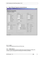
Page 3: ...imum Temperature 12 7 6 5 Operational temperature max Only available on certain GUI 12 7 6 6 Maximum Temperature Only available on certain GUI 12 7 7 Report 13 7 7 1 Set point 13 7 7 2 Temperature 13 7 7 3 Control 13 7 7 4 Output 13 7 7 5 Alarms 13 7 7 6 Faults 13 7 7 7 Temperature OK 13 7 8 Reading and Setting Parameters 13 7 8 1 Read Button 13 7 8 2 Write Button 13 7 9 Figure TC M series Tempera...

Page 4: ...TC M Temperature Controller User Manual V1 08 Electron Dynamics Ltd page 3 10 Sources of Information 17 There is a lot of information on the internet with some of it relevant have a look at these 17 ...

Page 5: ...ise temperature control system would be with laser diodes infrared detection high gain amplifiers and cold plate assemblies The TC M series temperature controller is suitable for controlling single and multiple TEC arrays It provides a pulse width modulated output which effective provides a continuously variable output for cooling and heating It is programmable from a PC allowing configuration and...

Page 6: ...ge Voltage sensors accuracy 0 01 mv or better 2 2 CPU This provides all the intelligent control measuring the input values and calculating the output required for the control type It also provides storage for the configuration parameters 2 3 Output driver This provides a bi directional variable output drive to the TEC element s The output switches at the preset repetition rate and adjusting for ou...

Page 7: ...urements For voltage outputs sensors LM35 LM50 LM51 LM 60 LM 61 configure the following links on the TCM PCB Lk1 link pins 1 and 2 Lk2 link pins 2 and 3 No other connections Connect sensor to J8 Sensor to pin 1 sensor output to pin 3 and sensor gnd to pin4 with screen if used to pin 6 In this configuration LM35 operates down to zero degrees C but not below 3 4 NTC thermistors To connect NTC thermi...

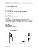
Page 8: ... low 3 9 Inhibit This is provide from J1 and inhibits the drive when the pins of j1 are connected together For multiple uses the TCM temperature controller can be made to inhibit control of other TCM controllers by its alarm output indicated by LED2 To achieve this the alarm output will need to be daisy chained to the inhibit switch of the respective controller 3 10 USB This is provided from J5 No...

Page 9: ...ensive material available from the peltier TEC manufacturers to find out the requirements for this See www marlow com and www lairdtech com 5 2 1 Heat sink size The size of this should be chosen using the manufacturers calculations it will need to be large enough to radiate the heat required typically they have a large heat capacity but often are more limited in there capability to dissipate the h...

Page 10: ...es Where the maximum drive is 100 So to reduce a 12v device to half power if we are powered at 12v then the max and mins should be 50 and 50 The situation if powered from 9v would be 9 12 100 75 5 6 Important stability issues Some important factors to remember Facilitate faster settling time and response by reducing thermal mass of sample reduce distance between TEC and item being cooled Improve a...

Page 11: ...s with the rate of the input error or output This provides a faster response to temperature variations and also provides a stability balancing effect to the integral term Please note that for best stability there must be a fixed ratio between the I term and the D term normally 4 to 1 Due to the inherently large gain of the derivative at high frequencies at filter the derivative TC is provided to a...

Page 12: ...pective terms can be calculated Td is Process time constant t is pseudo dead time and Kp the process gain From this the PID terms are calculated P term is 1 2 t Td Kp I term is Td 0 5 and D term is Td 0 5 6 8 Ziegler Nichols closed loop ultimate gain method This is a closed loop so the control function in on With the P term set low and the I term and D term off Monitoring the temperature the gain ...

Page 13: ... and opened at the outset in order to communicate with the controller 7 1 3 Help Displays help information 7 2 Control 7 2 1 Type The control algorithm can be single or a combination of Proportional Integral Derivative terms The list box allows the user to define the controller terms required The available options are 0 None 1 On Off 2 Proportional 3 Proportional and Integral 4 Proportional Integr...

Page 14: ...2 6 Derivative With derivative action the controller output is proportional to the rate of change of the measurement or error The controller output is calculated by the rate of change of the measurement with time in seconds To increase the derivative action increase the derivative value See also Derivative Filter 7 2 7 Derivative Filter The derivative filter is a low pass filter function on the de...

Page 15: ...ridden by the control Range 0 to 1000 7 4 Sensor 7 4 1 Type The supported sensor types are selectable from the list box refer to the specification section 7 6 in this manual for supported temperature sensors 7 4 2 X2 X C Coefficients These are quadratic coefficients than can be input to convert the sensor voltage measured into a temperature This can be used for other sensors so that these can cali...

Page 16: ...5 4 Frequency Sets the PWM repetition frequency of the output drive Range 20 to 1000 Hz 7 6 Alarms 7 6 1 Minimum Alarm Sets the temperature below which the alarm is activated Select via check box to enable 7 6 2 Maximum Alarm Sets the temperature above which the alarm is activated Select via check box to enable 7 6 3 Minimum OK Temperature Sets the lower temperature difference point from the set p...

Page 17: ...n 5 4 3 7 7 3 Control Displays the condition of the output drive either On or Off 7 7 4 Output Displays the output value is set to Range 0 to 1000 7 7 5 Alarms Displays whether an alarm is active 7 7 6 Faults Displays any fault codes 7 7 7 Temperature OK Displays if the temperature is in the ok range 7 8 Reading and Setting Parameters 7 8 1 Read Button The read button will load the respective GUI ...

Page 18: ...eries Temperature Controller GUI Java 7 10 C GUI There are minor differences with the Java GUI as below 7 10 1 Additional features The C GUI has feature for test mode temperature cycling and temperature ramping also included is an auto tuning algorithm for setting up the PID terms automatically ...

Page 19: ...les a continuous stream of temperature and output information from the TCM controller This is stored in a log file for compatible with excel for analysis This allows the user to measure response graphs for tuning and stability anaysis 7 10 3 C GUI 8 Communication Protocol Please see the commands file on the resources CD ROM ...

Page 20: ... Hysterysis Resolution 0 001 deg C Max stability 0 001 deg C depending on thermodynamics setup etc 9 4 Set point Set either by pot or by PC 9 5 Alarm PC configurable TTL output active low High temp Low temp or out of band 9 6 Sensor Voltage PT100 PT1000 LM35 LM50 LM60 LM61 NTC Thermistor OTHER Other versions can be calibrated using the quadratic coefficients 9 7 Measurement Accuraccy PT100 0 001 d...

Page 21: ...with some of it relevant have a look at these http www peltier info com TEC information site http www marlow com TEC manufacturer http www jashaw com pid Control E book http www jashaw com pid tutorial pid6 html PID tuning lecture notes http www brewerscience com cee otherprods cee_pid html PID notes http lorien ncl ac uk ming pid PID pdf PID notes ...

Reviews: