background image

14


14

5881

A

B

628

6238

15

  1 


9  11  1  15 

17  19

  2 

  4 

10  12  14  16 

18

1

4

2

12

15

14

16

1

18

11

Installation

Connection of external liquid  
supplies

Machines fitted with connectors

•  Connect the pump equipment to connections 

A and B on the washing machine.  
Connect the signal cable to B and the power 
supply to A.

Machines without connectors

•  Connect the external pump equipment for 

liquid washing detergent to the I/O board, 
which is located to the right of the incoming 
power supply.  
The I/O card has edge connectors for connec-
ting external pumps.

•  Edge connectors on the I/O board can be 

loosened for connecting cables. 


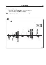
1 = N 
2 = L 
4 = Ground

11 = N 
18 = Program run 
12 = Signal 1 
1 = Signal 2 
14 = Signal  
15 = Signal 4 
16 = Signal 5

14

15

Summary of Contents for W455H

Page 1: ...Installation manual W455H 438 9067 51 EN 06 35 ...

Page 2: ......

Page 3: ... machine can only be used with water Never use dry cleaning agents Do not allow children to operate the machine Do not hose down or spray the machine with water All mechanical and electrical installation must be carried out by qualified personnel Do not bypass the door locking device Should the machine malfunction please report the fault to the technician responsible for the machine The manufactur...

Page 4: ......

Page 5: ...es 53 diameter mm 452 depth mm 332 Drum speed wash rpm 35 54 extraction 1300 Heating electricity kW 4 4 steam hot water x G factor 425 Weight net kg 102 Water valves connection DN20 BSP 3 4 Capacity at 300 kPa l min 17 Drain valve outer Ø mm 50 Draining capacity l min 160 ...

Page 6: ... H L 7 6206 A B C D E F G H I K L 595 680 850 875 305 660 80 195 60 90 80 650 1 Control panel 2 Soap box 3 Door opening ø255 4 Cold water 5 Hot water 6 Drain valve 7 Drain pump 8 Electrical connection Adjustable height 25 mm Technical data ...

Page 7: ...r load at extraction kN 1 2 0 3 Sound levels A B Solid sound level in dB A re 10 9 mm sec 44 707 Hz 76 62 Airborne sound level dB A re 2x10 5 Pa 51 71 45 59 Vibration level m sec2 0 36 0 66 Vibration speed mm sec 57 83 A Standard B With insulation Wash extraction ...

Page 8: ... ...

Page 9: ...n waste water channel The following clearances are recommended for easier installation and servicing at least 500 mm between the machine and the wall behind it at least 50 mm on each side of the machine whether it is next to a wall or to other machi nes A clearance of 70 mm may be required bet ween the machine and the 130 litre tumble dryer depending on which way the dryer s door opens Rec 50 mm R...

Page 10: ...cking devices step by step Remove the packaging Remove the components shipped inside the drum Remove the front panel by undoing the two screws on its bottom edge Remove the rear panel by undoing the screws Remove the three transport securities one at the front and two at the back Save the trans port securities if the machine needs to be moved sometime in the future Installation 2 3 ...

Page 11: ...ottom frame Place the machine over the two drilled holes Check that the machine is placed in level Adjust with the feet It is of the upmost importance that the machine is placed in level from side to side as well as front to rear If the machine is not properly levelled it may result in out of balance without a real out of balance in the drum Insert the expansion bolts supplied into the holes drill...

Page 12: ...ry of use Water pressures minimum 40 kPa 0 4 kp cm2 maximum 1 MPa 10 kp cm2 recommended 0 2 0 5 MPa 2 5 kp cm2 Hoses and pipes should be flushed through be fore being connected to the machine Make sure the hoses have no sharp bends or angles The machine can have one or two supply hoses DN 20 R 3 4 Machine with cold water intake only Machine with hot and cold water intake Machine with hot and cold ...

Page 13: ...drain hose to the machine s drain out let and install so it empties min 25 mm above the floor drain or waste water channel Pump drain Position the highest part of the drain hose 650 50 mm above the lowest part of the mach ine Make sure that there are no kinks in the hose 8 9 ...

Page 14: ...ion Electrical installation must be carried out by an authorised electrician Install a multi pole switch for the machine s electrical supply Connect the machine s cable to the switch Check that the earth has been connected in the correct way Fuse ratings are given in the table For the rating of the supply cable check the local regulations Min outer diameter for supply cable ø10 mm Heating Voltage ...

Page 15: ... lowing the options set out below The machine cannot be switched from 50 Hz to 60 Hz or vice versa Reconnection switchover of this type can not be performed on machines fitted with a transformer Connection option 400 V 3NAC 4 4 kW Connection option 230 V 3AC 4 4 kW Connection option 230 V 1AC 4 4 kW Connection option 230 V 1AC 2 2 kW In cases where the machine data plate does not state the new vol...

Page 16: ...Connect the signal cable to B and the power supply to A Machines without connectors Connect the external pump equipment for liquid washing detergent to the I O board which is located to the right of the incoming power supply The I O card has edge connectors for connec ting external pumps Edge connectors on the I O board can be loosened for connecting cables 1 N 2 L 4 Ground 11 N 18 Program run 12 ...

Page 17: ...4 Washing detergent signal 3 15 Washing detergent signal 4 16 Washing detergent signal 5 Inputs The signal level can be 5 24V DC AC or 100 240V AC For 5 24V the signal reference is connected to 3 and for 100 240V to 4 Poten tials on the inputs cannot be mixed NB The I O board will be damaged if the vol tage on connection 3 is too high 24V 3M14 3F01 3R01 3F02 Other programs Signal 1 Prewash Prewash...

Page 18: ...e displayed if any of the chemi cal tanks are empty The washing program will continue however Fit the connecting unions provided and con nect the hoses to the unions Detergent tank Empty Dosing system Pause signal Connection 8 can be connected if the washing program is to pause e g while washing detergent is being dosed 17 18 19 ...

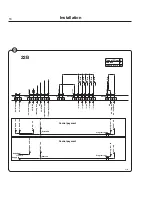
Page 19: ... 12 13 14 15 16 Liq 1 Liq 2 Liq 3 Liq 4 Liq 5 1 2 3 4 5 6 17 18 19 Out CO Con 107 1 2 3 230V 08 Prog run RE106 RE105 RE104 RE103 RE102 RE101 Function I O s Address Type of I O card 2 E 2 Installation Functions for I O cards Check the electrical schematic for the machine to find out what functions are available for the machine The electrical schematic can have one of the following 22E 22B 22C or 22...

Page 20: ...08 P out Inp opt Con 110 04 N inputs 04 L inputs 04 N inp 04 Common 24V 05 START Blocking start Liquid tank empty Temporary paus 05 1 2 1 2 3 4 5 6 1 2 3 4 5 6 7 8 V in Con 108 1 2 9 10 Out 5NO Con 109 Liq 1 Liq 2 Liq 3 Liq 4 Liq 5 1 2 3 4 5 6 11 12 13 14 15 16 Con 107 1 2 3 17 18 19 Out CO 24V 230V 08 08 Prog run RE106 RE105 RE104 RE103 RE102 RE101 Address Type of I O card Function I O s 2 B 2 20...

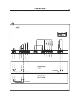
Page 21: ...puts 04 L inputs 04 N inp Common 24V 05 Blocking start Liquid tank empty Temporary paus Heating pause Liq 1 Liq 2 Liq 3 Liq 4 Liq 5 1 2 P out Con 111 1 2 3 4 5 Inp opt Con 110 1 2 3 4 5 6 6 7 8 9 10 V in Con 108 1 2 11 12 13 Out 5NO Con 109 1 2 3 4 5 6 14 15 16 RE106 RE105 RE104 RE103 RE102 17 18 19 Out CO Con 107 1 2 3 08 Machine free 08 Power RE101 Function I O s Address Type of I O card 2 C 2 2...

Page 22: ...on 110 1 2 3 4 5 6 1 2 3 4 5 Inp opt 6 7 8 04 N inputs 04 L inputs 04 N inp Liquid tank empty Temporary paus Heating pause 05 Price red 04 Com 24V 9 10 V in Con 108 1 2 11 12 13 Out 5NO Con 109 1 2 3 4 5 6 14 15 16 Liq 1 Liq 2 Liq 3 Liq 4 Liq 5 RE106 RE105 RE104 RE103 RE102 17 18 19 Out CO Con 107 1 2 3 RE101 Prog run Power Function I O s Address Type of I O card 2 D 2 20 22D 6314 Installation ...

Page 23: ...ne installation This machine can be installed in marine installa tion The maximum value for rolling is 15 and for stamping 8 The machine shall be placed as shown in fig Mark the two holes A on the floor plate on the site of machine installation Drill the two holes with ø 8 5 mm Thread the holes with M 10 21 22 23 24 ...

Page 24: ...e four feet of the machine as much as possible Place the machine at its site Place the spacers B between machine and floor Tighten the machine to the floor with the two bolts Adjust the feet of the machine to the floor and lock them with the nuts 25 26 27 ...

Page 25: ...hine Put detergent into compartment 2 Main wash Select a 60 program with the control knob 1 Press the knob Check that the drum rotates normally and that there are no unusual noises that there are no leaks in water supply drain connections that water passes through the detergent compartment and fabric conditioner compart ment that the door cannot be opened during a pro gram 1 2 ...

Page 26: ......

Page 27: ......

Page 28: ...www electrolux com professional Share more of our thinking at www electrolux com ...

Reviews: