background image

3

TSE-N /  A.S.

February 2002

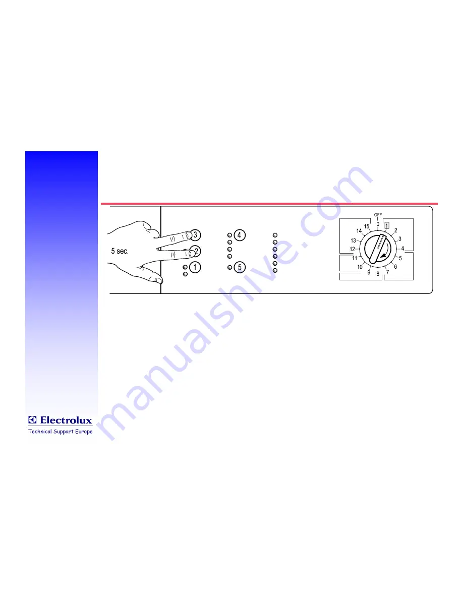
Diagnostic mode

Access (vertical configuration)

To enter the diagnostic mode, press the upper
two pushbuttons on the left-hand side simul-
taneously (irrespective of their function), and
turn programme selector to the first position
clockwise, until LEDs start flashing.

Summary of Contents for EWM1000

Page 1: ...1 TSE N A S February 2002 EWM 1000 DIAGNOSTICS FAULTFINDING ...

Page 2: ...c mode Access To enter the diagnostic mode press START PAUSE and one option button simultaneously and turn programme selector to the first position clockwise until LEDs start flashing position of pushbuttons is configurable and may vary ...

Page 3: ...ccess vertical configuration To enter the diagnostic mode press the upper two pushbuttons on the left hand side simul taneously irrespective of their function and turn programme selector to the first position clockwise until LEDs start flashing ...

Page 4: ...ostic mode Component actuation 1 Checked functions User interface functionality Actuated components all LEDs light in sequence if a pushbutton is depressed the corresponding LED lights and buzzer sounds if applicable Conditions none ...

Page 5: ...02 Diagnostic mode Component actuation 2 Checked functions Water fill main wash compartment Actuated components Door lock Main wash solenoid valve Conditions door closed water level below safety overflow level time out 5 min ...

Page 6: ...2002 Diagnostic mode Component actuation 3 Checked functions Water fill prewash compartment Actuated components Door lock Prewash solenoid valve Conditions door closed water level below safety overflow level time out 5 min ...

Page 7: ...e Component actuation 4 Checked functions Water fill fabric conditioner compartmt Actuated components Door lock Main wash and prewash solenoid valves simultaneously Conditions door closed water level below safety overflow level time out 5 min ...

Page 8: ...8 TSE N A S February 2002 Diagnostic mode Component actuation 5 Not applicable to EWM1000 machines checks 3rd solenoid valve ...

Page 9: ...onent actuation 6 Checked functions Heating Actuated components Door lock Main wash solenoid valve if level below first level Heating element Conditions door closed water level above first level water temperature below 80 C time out 10 min or 90 C ...

Page 10: ...onent actuation 7 Checked functions Tub leakage test Actuated components Door lock Main wash solenoid valve if level below first level Motor 55 rpm CW 55 rpm CCW 250 rpm impulse with water in tub Conditions door closed water level above first level ...

Page 11: ...omponent actuation 8 Checked functions Draining Spinning Pressure switch level congruence Actuated components Door lock Drain pump Motor 650 rpm then max spin speed Conditions door closed water level below antiboil level at start of spin movement ...

Page 12: ...12 TSE N A S February 2002 Diagnostic mode Component actuation 9 Not applicable to front loaded machines checks 3rd drum self positioning ...

Page 13: ...13 TSE N A S February 2002 Diagnostic mode Reading the last alarm code If an alarm code is stored in the EEPROM this will be shown in hexadecimal code by 2 flashing LEDs CYCLE END and START PAUSE ...

Page 14: ...14 TSE N A S February 2002 Diagnostic mode Reading the last alarm code If an alarm code is stored in the EEPROM this will be shown by 2 flashing LEDs CYCLE END and START PAUSE ...

Page 15: ... ØSTART PAUSE shows the second digit Øthe digits will be shown by a sequence of flashes 0 4 secs on 0 4 secs off Øafter a pause of 2 5 secs the sequence will be repeated Diagnostic mode Reading the last alarm code HEX digit 1 2 3 4 5 6 7 8 9 A B F Number of flashes 1 2 3 4 5 6 7 8 9 10 11 15 ...

Page 16: ...Diagnostic mode Reading the last alarm code An example code E43 LED CYCLE END LED START PAUSE On off Time secs Value On off Time secs Value 0 4 0 4 0 4 1 0 4 1 0 4 0 4 0 4 2 0 4 2 0 4 0 4 0 4 3 0 4 3 0 4 0 4 4 2 5 Pause 3 3 Pause ...

Page 17: ...002 Diagnostic mode Cancel the last alarm code ØMachine in diagnostic mode programme selector in position 10 ØPress START PAUSE and any option push button simultaneously for at least 2 secs ØAll LEDs start flashing to confirm ...

Page 18: ...ic mode Cancel alarm code vertical configuration ØMachine in diagnostic mode programme selector in position 10 ØPress the upper two pushbuttons on the left hand side simultaneously for at least 2 secs ØAll LEDs start flashing to confirm ...

Page 19: ...ry 2002 Diagnostic mode Exit Øto exit the diagnostic mode switch OFF the appliance Øthen switch it ON and switch it OFF AGAIN this is to avoid the machine go into factory test mode when a diagnostic mode is selected again ...

Page 20: ...ly first digit of the code LED CYCLE END On off Time secs Value 0 4 1 0 4 0 4 2 0 4 0 4 3 0 4 0 4 4 0 4 2 5 Pause is shown to the user by the flashing LED CYCLE END Øfor example E41 or E43 will be shown as Øalarm conditions E61 E83 or EA1 will not be shown to the user in any way ...

Page 21: ...n be read even if the machine is not in the diagnostic mode ØPress START PAUSE and any option pushbutton simultaneously for at least 2 seconds Ø All LEDs extinguish an then show the full alarm code ØThe sequence will be repeated as long as the 2 pushbuttons are kept depressed ...

Page 22: ...22 TSE N A S February 2002 Alarm code family 1 Water fill ØE11 water fill problems in wash cycle time out expired ØE13 water leakage ...

Page 23: ...23 TSE N A S February 2002 Alarm code family 2 Draining ØE21 drain problems time out expired ØE23 drain pump triac failure ØE24 drain pump triac sensing failure ...

Page 24: ...tch ØE33 incongruency between antiboil and 1st level switches longer than 3 secs ØE35 water overfill antiflood level switch open for more than 15 seconds ØE36 antiboil sensing AB_S failure ØE37 1st level sensing L1_S failure ØE39 antiflood sensing HV1_S failure ...

Page 25: ...SE N A S February 2002 Alarm code family 4 Door lock ØE41 door open time out expired ØE42 door lock failure ØE43 door lock triac failure ØE44 closed door sensing failure ØE45 door lock triac sensing failure ...

Page 26: ...SE N A S February 2002 Alarm code family 5 Motor circuit ØE51 motor triac short circuit ØE52 no tachometer signal from motor ØE53 motor triac sensing failure ØE54 motor reversing relay contact always closed ...

Page 27: ...y 2002 Alarm code family 6 Heating circuit ØE61 insufficient heating in wash cycle time out expired NOT SHOWN IN USER MODE ØE62 overheating during wash cycle temp on NTC 88 C for more than 5 min ØE66 heating relay failure ...

Page 28: ...28 TSE N A S February 2002 Alarm code family 7 NTC sensor ØE71 NTC sensor failure value out of limits ...

Page 29: ...29 TSE N A S February 2002 Alarm code family 8 Programme selector ØE82 wrong selector reset position selection ØE83 wrong selector reading NOT SHOWN IN USER MODE ...

Page 30: ...E93 machine configuration error ØE94 cycle configuration error ØE95 communication error between microprocessor and EEPROM ØE96 incongruence between circuit board configuration and hardware ØE97 incongruence between programme selector and cycle configuration table ...

Page 31: ...31 TSE N A S February 2002 Alarm code family A DSP ØEA1 DSP door self positioning on top loaded machines only NOT SHOWN IN USER MODE ...

Page 32: ...32 TSE N A S February 2002 Alarm code family B Power supply ØEB1 power supply frequency out of limits ØEB2 power supply voltage too high ØEB3 power supply voltage too low ...

Page 33: ...33 TSE N A S February 2002 Component Diagnostic Connector Identification ...

Page 34: ...34 TSE N A S February 2002 Component Diagnostic J1 Motor connector J1 1 to J1 2 full stator winding 1 3 Ω depending on type of motor ...

Page 35: ...35 TSE N A S February 2002 Component Diagnostic J1 Motor connector J1 1 to J1 3 half stator winding 0 5 1 5 Ω on machines with 1400 rpm depending on type of motor ...

Page 36: ...36 TSE N A S February 2002 Component Diagnostic J1 Motor connector J1 4 to J1 5 rotor winding 1 5 3 Ω depending on type of motor ...

Page 37: ...37 TSE N A S February 2002 Motors ...

Page 38: ...38 TSE N A S February 2002 Component Diagnostic J2 J6 Door lock Pressure switches BIMETAL PTC DOOR LOCK J2 4 to J6 2 door lock bimetal PTC about 1 Ω ...

Page 39: ...39 TSE N A S February 2002 Component Diagnostic J2 J6 Door lock Pressure switches INSTANTANEOUS DOOR LOCK J2 4 to J6 2 solenoid PTC protector about 200 Ω ...

Page 40: ...40 TSE N A S February 2002 Component Diagnostic J2 J6 Door lock Pressure switches INSTANTANEOUS DOOR LOCK J2 5 to J6 2 bimetal PTC about 1 kΩ ...

Page 41: ...41 TSE N A S February 2002 Component Diagnostic J2 J6 Door lock Pressure switches INSTANTANEOUS DOOR LOCK J2 4 to J2 5 solenoid PTC protector bimetal PTC about 1 2 kΩ ...

Page 42: ...42 TSE N A S February 2002 Component Diagnostic J2 J6 Door lock Pressure switches ALL DOOR LOCKS J2 1 to J6 2 door switch open or closed ...

Page 43: ...43 TSE N A S February 2002 Component Diagnostic J2 J6 Door lock Pressure switches J2 1 to J2 2 1st level press switch open if water below 1st level closed if above ...

Page 44: ...44 TSE N A S February 2002 Component Diagnostic J2 J6 Door lock Pressure switches J6 1 to J2 2 antiboil level press switch open if water below this level heating element resistance about 30 Ω if above ...

Page 45: ...45 TSE N A S February 2002 Component Diagnostic J2 J6 Door lock Pressure switches J2 3 to J2 6 antiflood level press switch not on all models normally closed ...

Page 46: ...46 TSE N A S February 2002 Component Diagnostic J3 Solenoid Valves and Drain Pump J3 2 to J3 5 prewash solenoid valve about 3 75 kΩ ...

Page 47: ...47 TSE N A S February 2002 Component Diagnostic J3 Solenoid Valves and Drain Pump J3 6 to J3 7 main wash solenoid valve about 3 75 kΩ ...

Page 48: ...48 TSE N A S February 2002 Component Diagnostic J3 Solenoid Valves and Drain Pump J3 1 to J3 4 drain pump motor about 170 Ω ...

Page 49: ...49 TSE N A S February 2002 Component Diagnostic J5 NTC and Tachogenerator J5 1 to J5 2 NTC sensor about 6 kΩ at room temperature see sensor characteristic for values at other temperatures ...

Page 50: ...50 TSE N A S February 2002 NTC Characteristic ...

Page 51: ...51 TSE N A S February 2002 Component Diagnostic J5 NTC and Tachogenerator J5 1 to J5 2 tachogenerator 65 to 540 Ω depending on motor type If motor is rotated by hand a low AC voltage can be measured ...

Page 52: ...52 TSE N A S February 2002 Motors ...

Page 53: ...53 TSE N A S February 2002 Component Diagnostic J4 Provision for Door Pilot Lamp J4 1 to J4 2 door pilot lamp only on few models ...

Page 54: ... TSE N A S February 2002 Component Diagnostic And J7 J7 is the external serial interface It may be used to connect the circuit board to a computer and run configuration or diagnostic programmes from there ...

Reviews: