Electrolux Professional S.p.A.
Ovens Platform Customer Support
Technical Training & Service
AOS OVENS - Service Manual
(595889300 – ENG)
13. Gas system
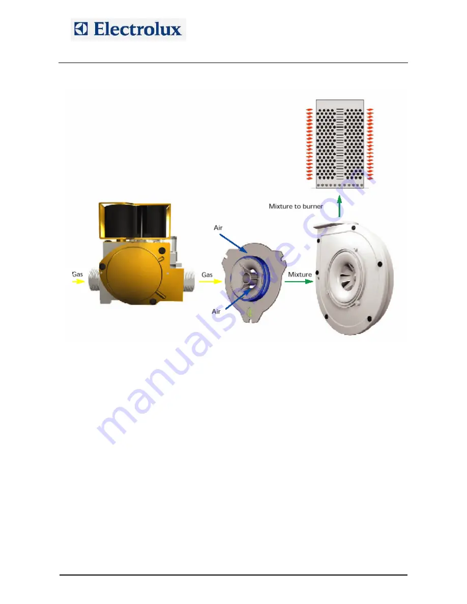
The gas system is made with low emission burners. The main components are:
SIT gas valve type SIGMA 848
DC burner fan that is intaking air through a calibrated mixer where the air–gas mixture is created; then
the fun conveys the mixture to the burner
A cavity and a boiler heat exchanger made with a corrugated tube for increasing the efficiency
An ignition rod and a detection rod
An ignition device.
Starting with a cooking cycle, the POW board of the oven activates the ignition device which activates the
burner fan whose speed is controlled with a PWM signal.
The POW board activates the ignition device. Form pin 8 of the ignition device a high voltage output is
carried to the digital input section of the POW board (X10/5÷8) and to the switching feeder for the burner
fans.
With an high voltage input on X10/5÷8, the POW board generates on X9/2÷5 a PWM signal to control the
speed of the burner fans, i.e. controlling the quantity of sucked gas and air. The PWM signal changes
according to the status of the burner, i.e.:
Start of the burner: controlled with parameters
StcA
(start of cavity burners) and
Stbo
(start of boiler
burners).
Full power of the burner: controlled with parameters
FucA
(full power of cavity burners) and
Fubo
(full
power of boiler burners)
Half power of the burner: controlled with parameters
hAcA
(half power of cavity burners) and
hAbo
(half
power of boiler burners)
The quantity of sucked gas is controlled with those parameters (which are determining the speed of the
burner fans), with the injector/diaphragm inserted at the outlet of the gas valve and with the calibration of the
offset value on the gas valve.
The quantity of sucked air is controlled with the above parameters and with the calibrated aerator on the
mixer.
The ignition sequence is then the following:
File: AOS service manual (ENG).008
©Copyright 2002 by Electrolux Professional
P.13/40


