background image

Installation Instructions

24

Installation Instructions

1

Safety instructions

Warning! This must be read!
The laws, ordinances, directives and standards in force in the country of use are 
to be followed (safety regulations, proper recycling in accordance with the regu
lations, etc.)
Installation may only be carried out by a qualified electrician.
The minimum distances to other appliances and units are to be observed.
Antishock protection must be provided by the installation, for example drawers 
may only be installed with a protective floor directly underneath the appliance.
The cut surfaces of the worktop are to be protected against moisture using a 
suitable sealant.
The sealant seals the appliance to the work top with no gap.
When building in, protect the underside of the appliance from steam and mois
ture, e.g. from a dishwasher or oven.
Avoid installing the appliance next to doors and under windows. Otherwise hot 
cookware may be knocked off the rings when doors and windows are opened.

z

Risk of injury from electrical current.

The electrical mains terminal is live.

Make electrical mains terminal free of voltage.

Follow connection schematic.

Observe electrical safety rules.

Ensure antishock protection by installing correctly.

The appliance must be connected to the electrical supply by a qualified electrician.

z

Risk of injury from electrical current.

Loose and inappropriate plug and socket connections can make the terminal overheat.

Have the clamping connections correctly installed by a qualified electrician.

Use strain relief clamp on cable.

In the event of singlephase or twophase connection, the appropriate mains 
cable of type H05BBF Tmax 90°C (or higher) must be used.

If this appliance’s mains cable is damaged, it must be replaced by a special ca
ble (type H05BBF Tmax 90°C; or higher). Please contact your local Service 
Force Center for further advice.

A device must be provided in the electrical installation which allows the appli
ance to be disconnected from the mains at all poles with a contact opening 
width of at least 3 mm 
Suitable isolation devices include line protecting cutouts, fuses (screw type fus
es are to be removed from the holder), earth leakage trips and contactors.

Summary of Contents for 98001 KF SN

Page 1: ...98001 KF SN User manual Ceramic hob ...

Page 2: ...s To ensure optimal and regular performance of your appliance please read this instruction manual carefully It will enable you to navigate all processes perfect ly and most efficiently To refer to this manual any time you need to we recommend you to keep it in a safe place And please pass it to any future owner of the appliance We wish you much joy with your new appliance The following symbols are...

Page 3: ...tion on and off 9 Using the automatic warm up function 10 Locking unlocking the control panel 11 Using the child safety device 12 Switching the power function on and off 13 Using the timer 14 Automatic switch off 17 Tips on cooking and frying 18 Cookware for induction cooking zones 18 Tips on energy saving 18 Examples of cooking applications 19 Cleaning and care 20 What to do if 21 Disposal 23 Ins...

Page 4: ...ace or store flammable liquids highly inflammable materials or fusi ble objects e g plastic film plastic aluminium on or near the appliance Child safety Small children must be kept away from the appliance Only let bigger children work on the appliance under supervision To avoid small children and pets unintentionally switching the appliance on we recommend activation of the child safety device Gen...

Page 5: ...leaning the appliance must be switched off and cooled down For safety reasons the cleaning of the appliance with steam jet or high pres sure cleaning equipment is not permitted How to avoid damage to the appliance The ceramic glass can be damaged by objects falling onto it The edge of the ceramic glass can be damaged by being knocked by the cook ware Cookware made of cast iron cast aluminium or wi...

Page 6: ... Description of the Appliance Cooking surface layout Induction cooking zone 2300W with power function 3200W Induction cooking zone 2300W with power function 3200W Control panel Induction cooking zone 2300W with power function 3200W ...

Page 7: ... heat emitted Lengthy cooking on higher settings with larger cookware on the front cooking zones can heat the sensor fields Take care when touching sensor fields Sensor field Function On Off Switches appliance on and off Increase settings Increasing heat setting time Decrease settings Decreasing heat setting time Timer Timer selection Lock Locking unlocking the control panel Power Switching the po...

Page 8: ...hes itself on and off depending upon the temperature of the electronics Display Description Cooking zone is switched off u Keep warm setting Keep warm setting STOP GO function is set Ç Heat settings Heat setting is set 2 6 Heating setting plus decimal point Intermediate heat setting is set a Automatic warm up func tion Automatic warm up function is acti vated e Fault Malfunction has occurred f Pan...

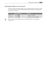
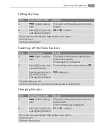
Page 9: ...d off The STOP GO function simultaneously switches all cooking zones that are switched on to the keep warm setting and then back to the heat setting that was previously set 3 Timer functions are not stopped by 3 locks the whole control panel except the sensor field Control panel Display Pilot light Switch on Touch for 2 seconds h lights up Switch off Touch for 1 second h none goes out Control pane...

Page 10: ...ing is selected e g from Á to à the automatic warm up is adjusted The length of time that the automatic warm up function operates depends on the heat setting selected Step Control panel Display 1 Setting the maximum setting Ç p 2 Place to one side for a moment Ç p 3 touch a 4 touch in order to set the desired cooking setting Æ until u after 3 seconds a Heat setting Length of the automatic warm up ...

Page 11: ... sensor field can be locked at any time in order to prevent the settings being changed e g by wiping over the panel with a cloth 3 When you switch the appliance off the locking function is automatically switched off Control panel Display Switch on Touch l for 5 seconds Switch off Touch previously set heat setting ...

Page 12: ...ep Control panel Display Signal 1 Switch on the appliance Do not set a heat setting 2 Touch until the signal sounds Acoustic signal 3 Touch l Appliance switches off The child safety device is set Step Control panel Display Signal 1 Switch on the appliance l 2 Touch until the signal sounds Acoustic signal 3 Touch Appliance switches off The child safety device is released Step Control panel Display ...

Page 13: ...ion can always be carried out Power Management may re duce the power of the other cooking zone in the pair Example heat setting 9 is selected on a cooking zone The Power function is switched on for the cooking zone paired up with it The Power function is performed but heat setting 9 on one cooking zone and Power function on the other cook ing zone of a pair exceeds the maximum output for both Ther...

Page 14: ...ht is flashing more slowly the heat setting indicator appears again and the heat setting can be re set or modified 3 If other timer functions are set after a few seconds the shortest remaining time of all the timer functions is displayed and the corresponding pilot light flashes Function Condition Outcome after the time has elapsed Automatic cut out a heat setting is set acoustic signal 00 flashes...

Page 15: ...ht of the selected cooking zone flashes more quickly Remaining time is displayed 2 Touch for the cook ing zone selected The remaining time counts down to 00 Simultaneoulsy touch and for the cooking zone selected 00 is displayed The pilot light goes out The Timer function for the selected cooking zone is switched off Step Control panel field Display 1 Select cooking zone Pilot light of the cooking ...

Page 16: ...ignal Step Control panel field Display 1 Select cooking zone Pilot light of the cooking zone selected flashes faster The time remaining is displayed After a few seconds the pilot light flashes more slowly Step Control panel field Acoustic signal 1 Touch Acoustic signal to acknowledge Acoustic signal stops ...

Page 17: ...ed for more that 10 seconds an acoustic signal sounds The acoustic signal switches itself off automatically when the sensor fields are no longer covered Induction cooking zones In the event of overheating e g when a pan boils dry the cooking zone auto matically switches itself off _ is displayed Before being used again the cooking zone must be set to 0 and allowed to cool down If cookware that is ...

Page 18: ...rtain cookware can make noises when being used on induction cooking zones These noises are not a fault in the appliance and do not affect operation in any way Bottom of the cookware The bottom of the cookware should be as thick and flat as possible Pan size Induction cooking zones adapt automatically to the size of the bottom of the cook ware up to a certain limit However the magnetic part of the ...

Page 19: ...e as much liquid as rice stir milk dishes part way through cooking 3 4 Steaming Braising Steaming vegetables fish Braising meat 20 45 mins With vegetables add only a little liquid a few table spoons 4 5 Boiling Steaming potatoes 20 60 mins Use only a little liquid e g max l water for 750 g of potatoes Cooking larger quantities of food stews and soups 60 150 mins Up to 3 l liquid plus in gredients ...

Page 20: ...er the surface 3 Wipe the appliance with a damp cloth and a little washing up liquid 4 Rub the appliance dry using a clean cloth Scrapers and cleaners for glass ceramic and stainless steel can be purchased in specialist shops supermar kets the parts department of your local Service Force Centre or from www shop electrolux co uk 3 Remove stubborn residues with a cleaner for glass ceramic or stainle...

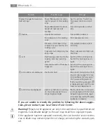
Page 21: ...ooking zone is sup posed to be hot call your local Service Force Centre The automatic warm up func tion is not switching itself on There is still residual heat on the cooking zone h Let the cooking zone cool down The highest heat setting is set Ç The highest heat setting has the same power as the auto matic warm up function Sensor fields are getting hot Cookware too big or placed too near the cont...

Page 22: ...he cooking zone Put cookware on zone Diameter of the base of the cookware is too small for the cooking zone Use suitable cookware min 120 mm Cookware not completely cov ering cross Place cookware centrally over the cross _ is lit Overheating protection for the cooking zone has been trig gered Switch off the cooking zone Switch the cooking zone on again Automatic switch off has been triggered Switc...

Page 23: ... product may not be treated as household waste Instead it shall be handed over to the applicable collection point for the recycling of electrical and electronic equip ment By ensuring this product is disposed of correctly you will help prevent po tential negative consequences for the environment and human health which could otherwise be caused by inappropriate waste handling of this product For mo...

Page 24: ...Risk of injury from electrical current The electrical mains terminal is live Make electrical mains terminal free of voltage Follow connection schematic Observe electrical safety rules Ensure anti shock protection by installing correctly The appliance must be connected to the electrical supply by a qualified electrician z Risk of injury from electrical current Looseandinappropriateplugandsocketconn...

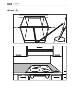
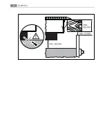
Page 25: ...he one sided self adhesive sealing tape supplied all the way round the lower edge of the cooking surface along the outer edge of the glass ceramic panel Do not stretch it The cut ends should lie in the middle of one side When you have cut it to length add a few mm press the two ends flush up against one another ...

Page 26: ...Assembly 26 Assembly ...

Page 27: ...27 Assembly ...

Page 28: ...Assembly 28 ...

Page 29: ...29 Assembly ...

Page 30: ...Assembly 30 ...

Page 31: ...31 Rating Plate 6 9 kW 55GDDE2AG 98001KF SN 6 9 kW 949 592 772 230 V 50 Hz AEG ELECTROLUX ...

Page 32: ...uctions The appliance has not been serviced maintained repaired taken apart or tam pered with by any person not authorised by us Electrolux Service Force Centre must undertake all service work under this guarantee Any appliance or defective part replaced shall become the Company s proper ty This guarantee is in addition to your statutory and other legal rights Exclusions Damage or calls resulting ...

Page 33: ...used for commercial purposes The appliance is installed in accordance with all relevant regulations in force within your new country of residence The provisions of this European Guarantee do not affect any of the rights granted to you by law p t b Albania 35 5 4 261 450 Rr Pjeter Bogdani Nr 7 Tirane Belgique België Belgien 32 2 363 04 44 Bergensesteenweg 719 1502 Lembeek Èeská republika 420 2 61 1...

Page 34: ...r Garii Progresului 2 S4 040671 RO Schweiz Suisse Svizzera 41 62 88 99 111 Industriestrasse 10 CH 5506 Mägenwil Slovenija 38 61 24 25 731 Electrolux Ljubljana d o o Gerbièeva 98 1000 Ljubljana Slovensko 421 2 43 33 43 22 Electrolux Slovakia s r o Electrolux Domáce spot rebièe SK Seberíniho 1 821 03 Bratislava Suomi www electrolux fi Sverige 46 0 771 76 76 76 Electrolux Service S t Göransgatan 143 ...

Page 35: ...ber 3 Clear and concise details of the fault 4 The model and serial number of the appliance found on the rating plate 5 The purchase date Please note that a valid purchase receipt or guarantee documentation is required for in guarantee service calls Customer Care For general enquiries concerning your AEG appliance or for further information on AEG products please contact our Customer Care Departme...

Page 36: ...www electrolux com www aeg electrolux co uk 867 200 302 M 290507 03 Subject to change without notice ...

Reviews: