background image

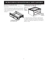
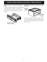
WARM & SERVE DRAWER INSTALLATION INSTRUCTIONS
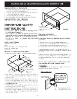
2

c

/

25 

5

/

16

(64,3 cm)

24" (61 cm) Max.

23 

5

/

8

" (60 cm) Min.

c

/

12 

21

/

32

(32,2 cm)

Figure 1

Important Notes to the Installer

1.  Read all instructions contained in these installation 

instructions before installing appliance.

2.  Remove all packing material from appliance before 

connecting the electrical supply.

3.  Observe all governing codes and ordinances.
4.  Be sure to leave these instructions with the consumer.

Important Note to the Consumer

Keep these instructions for future reference.

IMPORTANT SAFETY 
INSTRUCTIONS

 Be sure your appliance is installed and plugged into 

a 120 Volt grounded outlet.

• 

This appliance must be electrically grounded in 
accordance with the National Electrical Code ANSI/
NFPA No. 70—latest edition in the United States, 
or CSA C22.1, Part 1 in Canada, and local code 
requirements.

Tools You Will Need

Phillips® Screwdriver
Pencil
Ruler or Tape Measure and Straight-edge
Hand Saw or Saber Saw
Spirit Level

Warm & Serve Drawer Installation

1. Locate the 2 anti-tip brackets supplied as shown on fig. 1.
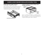
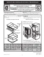
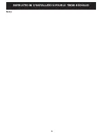
Figure 2

Use screws 
supplied to attach 
drawer to front of 
cabinet.

2. Slide drawer into cutout opening until front frame of  

drawer is flush against cabinet. Be careful not to pinch 
electrical cord.

3. Remove the drawer as instructed in the Use & Care 

Guide and secure drawer housing to cabinet using the 
3 nickel-plated screws supplied (see Figure 2). 

Do not 

overtighten screws.

4. The 60" (152,4 cm) appliance power cord can now be 

connected into the 120 Volt outlet.

5. Proceed with mounting built-in oven above the drawer (if 

applicable). Follow installation instructions provided with 
built-in oven. Make sure to use anti-tip brackets supplied 
with the built-in oven.

Electrical connection

IMPORTANT

 Please read carefully.

For personal safety, this appliance must be properly 
grounded.

The power cord of this appliance is equipped with a 
3-prong (grounding) plug which mates with a standard 
3-prong grounding wall receptacle to minimize the 
possibility of electric shock hazard from the appliance.

The wall receptacle and circuit should be checked by a 
qualified electrician to make sure the receptacle is properly 
grounded.

Where a standard 2-prong wall receptacle is installed, it is 
the personal responsibility and obligation of the consumer 
to have it replaced by a properly grounded 3-prong wall 
receptacle.

Do not, under any circumstances, cut or remove the 
third (ground) prong from the power cord.


Disconnect electrical supply cord from wall 

receptacle before servicing cooktop.
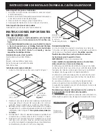
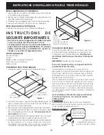
Preferred Method

Grounding type

wall receptacle

Do not, under any 

circumstances, cut, 

remove, or bypass 

the grounding 

prong.

Power supply cord with 

3-prong grounding plug.

Summary of Contents for 318201810

Page 1: ...t be lower than the warmer drawer cutout A HEIGHT B WIDTH C Depth 11 28 6 cm 30 76 2 cm 23 3 8 59 4 cm D cutout height E cutout width F cutout depth Min 9 7 8 25 1 cm 28 72 4 cm 24 61 cm Max 10 26 cm 28 73 cm A HEIGHT B WIDTH C Depth 11 28 6 cm 30 76 2 cm 23 3 8 59 4 cm D cutout height E cutout width F cutout depth G HEIGHt Min 9 7 8 25 1 cm 28 72 4 cm 24 61 cm 1 4 4 cm Max 10 26 cm 28 73 cm Depen...

Page 2: ...al cord 3 Remove the drawer as instructed in the Use Care Guide and secure drawer housing to cabinet using the 3 nickel plated screws supplied see Figure 2 Do not overtighten screws 4 The 60 152 4 cm appliance power cord can now be connected into the 120 Volt outlet 5 Proceed with mounting built in oven above the drawer if applicable Follow installation instructions provided with built in oven Mak...

Page 3: ...and serial numbers and a lot number or letter from the serial plate on your Warm Serve Drawer Serial Plate Location Combination Warm Serve Drawer and Cooktop Installation You can install the warmer drawer in combination with an electric or gas cooktop You must follow the specifications from the installation instructions of the cooktop to avoid interference with the gas or electric installation Coo...

Page 4: ...WARM SERVE DRAWER INSTALLATION INSTRUCTIONS 4 Notes ...

Page 5: ...alentador A ALTO B ANCHO C LARGO 11 28 6 cm 30 76 2 cm 23 3 8 59 4 cm D ALTURA DE LA ABERTURA E ANCHO DE LA ABERTURA F LARGO DE LA ABERTURA MÍn 9 7 8 25 1 cm 28 72 4 cm 24 61 cm Máx 10 26 cm 28 73 cm A ALTO B ANCHO C LARGO 11 28 6 cm 30 76 2 cm 23 3 8 59 4 cm D ALTURA DE LA ABERTURA E ANCHO DE LA ABERTURA F LARGO DE LA ABERTURA G ALTO Min 9 7 8 25 1 cm 28 72 4 cm 24 61 cm 1 4 4 cm Máx 10 26 cm 28 ...

Page 6: ...4 El cable de 60 152 cm del electrodoméstico puede ahora conectarse en un tomacorriente de 120 voltios con tierra 5 Proceda con el montaje del horno integrado por encima del cajón si es el caso Siga las instrucciones provistas con el horno integrado Asegúrese de usar las abrazaderas antideslizantes provistas con el horno integrado Figura 2 Utilizar los tornillos para fijar el cajón al frente del g...

Page 7: ...tra o número de la placa con el número de serie de su cajón calentador La placa de serie está ubicada aquí Combinación del cajón calentador y la instalación de una cubierta Se puede instalar el cajón calentador en combinación con una cubierta superior eléctrica o de gas Tiene que seguir las especificaciones de las instrucciones de instalación de la cubierta superior para evitar interferencia con l...

Page 8: ...8 INSTRUCCIONES DE Instalación PARA EL Cajón CALENTADOR Notas ...

Page 9: ...nsion critique et doit être respectée A hauteur B LARGEUR C PROFONDEUR 11 28 6 cm 30 76 2 cm 23 3 8 59 4 cm D HAUTEUR DU DÉCOUPAGE E LARGEUR DU DÉCOUPAGE F PROFONDEUR DU DÉCOUPAGE Min 9 7 8 25 1 cm 28 72 4 cm 24 61 cm Max 10 26 cm 28 73 cm A HAUTEUR B LARGEUR C PROFONDEUR 11 28 6 cm 30 76 2 cm 23 3 8 59 4 cm D HAUTEUR DU DÉCOUPAGE E LARGEUR DU DÉCOUPAGE F PROFONDEUR DU DÉCOUPAGE G HAUTEUR Min 9 7 ...

Page 10: ...océdezmaintenantaumontagedufourencastrésuperposé au tiroir réchaud s il y a lieu Suivez les instructions d installation fournies avec le four encastré Assurez vous d utiliser les crochets anti bascule fournis avec le four c c 25 5 16 64 3 cm 24 61 cm Max 23 5 8 60 cm Min c c 12 21 32 32 2 cm Figure 1 Figure 2 Utilisez les vis fournies pour fixer le châssis du tiroir à l armoire Connexion électriqu...

Page 11: ...s numéros de modèle et de série inscrits sur la plaque signalétique de votre appareil Emplacement de la plaque signalétique Installation combinée tiroir réchaud table de cuisson Vous pouvez installer le tiroir réchaud en combinaison avec une table de cuisson électrique ou gaz en respectant les contraintes imposées par le feuillet d installation de cette table afin d éviter certaines interférences ...

Page 12: ...12 INSTRUCTIONS D INSTALLATION POUR LE TIROIR RÉCHAUD Notes ...

Reviews: