


2-20
Installation
P/N 0013-1027-005 Rev A
The only reasonable filtering at the drive output terminals is the use of inductance. Capacitors
would slow the output switching and deteriorate the drive performance. A common mode
choke can be used to reduce the drive emissions. This will reduce emission coupling through
the drive back to the AC line. However, the motor cable still carries a large HF voltage and
current. In fact, the motor cable length directly affects the amplitude and frequency of the emis-
sions on the AC line. Therefore, it is very important to segregate the motor cable from the AC
power cable. For applications where long motor cables are required, the need for AC line filtering
increases.
Grounding
High frequency (HF) grounding is different from safety grounding. A long wire is sufficient for
a safety ground, but is completely ineffective as an HF ground due to the wire inductance. As
a rule of thumb, a wire has an inductance of 8 nH/cm (20 nH/in) regardless of diameter. At low
frequencies it acts as a constant impedance, at intermediate frequencies as an inductor, and at
high frequencies as an antenna. The use of ground straps is a better alternative to wires. However
the length to width ratio must be 5:1, or better yet 3:1, to remain a good high frequency
connection.
The ground system’s primary purpose is to function as a return current path. It is commonly
thought of as an equipotential circuit reference point, but different locations in a ground system
may be at different potentials. This is due to the return current flowing through the ground
systems finite impedance. In a sense, ground systems are the sewer systems of electronics and
as such are sometimes neglected.
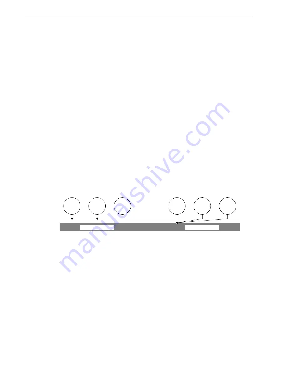
The primary objective of a high frequency ground system is to provide a well defined path for
HF currents and to minimize the loop area of the HF current paths. It is also important to separate
HF grounds from sensitive circuit grounds. A single point, parallel connected ground system
is recommended. Figure 2.15 shows single point grounds for both series (daisy chain) and par-
allel (separate) connections. Multiple drives should be connected to the AC source in a parallel
fashion.
A ground bus bar or plane should be used as the “single point” where circuits are grounded.
This will minimize common (ground) impedance noise coupling. The ground bus bar (GBB)
should be connected to the AC ground, and if necessary, to the enclosure. All circuits or sub-
systems should be connected to the GBB by separate connections. These connections should be
as short as possible, and straps should be used when possible. The motor ground conductor
must return to the ground terminal on the drive, not the GBB.
Shielding and Segregation
The EMI radiating from the drive enclosure drops off very quickly over distance. Mounting the
drive in a conductive enclosure, such as an industrial cabinet, further reduces the radiated
emissions. The cabinet should be set up to act as a Faraday cage. The cabinet should have a high
frequency ground and the size of openings should be minimized. All Electro-Craft drive ampli-
fiers must be mounted in an industrial cabinet to meet safety requirements.
Intro
F
IGURE
2.15
Single Point Ground Types
CIRCUIT
1
CIRCUIT
2
CIRCUIT
3
CIRCUIT
1
CIRCUIT
2
CIRCUIT
3
PARALLEL CONNECTION
SERIES CONNECTION
Ground Bus Bar
Summary of Contents for IQ 2000
Page 8: ...Intro 6 Contents P N 0013 1027 005 Rev A ...
Page 54: ...2 36 Installation P N 0013 1027 005 Rev A ...
Page 79: ...Wiring 3 25 IQ 2000 5000 Installation Manual 3Wiring FIGURE 3 25 IQ 5000 Power Wiring ...
Page 80: ...3 26 Wiring P N 0013 1027 005 Rev A FIGURE 3 26 PSM AUX Connections ...
Page 82: ...3 28 Wiring P N 0013 1027 005 Rev A FIGURE 3 28 IQ 2000 Power Wiring for PDM 75 ...
Page 88: ...3 34 Wiring P N 0013 1027 005 Rev A ...
Page 94: ...4 6 Applying Power for the First Time P N 0013 1027 005 Rev A ...
Page 104: ...6 4 Specifications P N 0013 1027 005 Rev A ...
Page 114: ...Help 6 EU Directives P N 0013 1027 005 Rev A ...


