

11
1/10 electrIc stadIuM truck
en
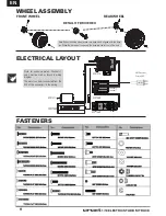
fasteners
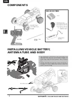
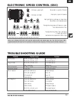
Note: For correct operation, Channels 1
and 2 must be used as shown in wiring
diagram.
The motor can be disconnected from the
ESC at the connectors in the wiring.
wheel assembly
front Wheel
detaIl of drIve hex
rear Wheel
Speed Controller
Receiver
Battery 7.2V
Motor
Steering Servo
CH.2
CH.1
ECX1069
ECX1068
ECX1070
ECX1071
DYN1050
Channel 2
Channel 1
Note: When installing wheel, make sure drive hex is aligned with the drive
pin. When the drive hex is removed, the drive pin can fall out of the axle.
AM Receiver
Crystal (RX)
electrical layout


