13-10
EXPLODED VIEWS AND SPARE PARTS LISTS
Revision Y05-02
Service Manual - Delta DCI
13.10
Outdoor Unit: DCR 50 DCI
Page 1: ...Service Manual DC Inverter Delta Series REFRIGERANT R410A HEAT PUMP JUNY 2005 Indoor Units Outdoor Units Delta 22 DCR 22 Delta 25 DCR 25 Delta 35 DCR 35 Delta 50 DCR 50...
Page 2: ...ssue for original and changed pages are Original 0 15 March 2005 Total number of pages in this publication is 79 consisting of the following Page No Revision No Page No Revision No Page No Revision No...
Page 3: ...ING CONDITIONS 3 1 4 OUTLINE DIMENSIONS 4 1 5 PERFORMANCE DATA PRESSURE CURVES 5 1 6 SOUND LEVEL CHARACTERISTICS 6 1 7 ELECTRICAL DATA 7 1 8 WIRING DIAGRAMS 8 1 9 REFRIGERATION DIAGRAMS 9 1 10 TUBING...
Page 4: ...red remote control with liquid crystal display Indoor large diameter cross ow fan allowing low noise level operation Bended indoor coil with treated aluminum ns and coating for improved ef ciency High...
Page 5: ...lter optional Active carbon lter optional 1 5 Control The microprocessor indoor controller and an infrared remote control supplied as standard provide complete operating function and programming For...
Page 6: ...cting tubing to be produced on site For further details please refer to the Installation Manual Appendix A 1 8 Inbox Documentation Each unit is supplied with its own installation and operation manuals...
Page 7: ...s per pallet units 36 units per pallet Stacking height units 9 levels OUTDOOR Refrigerant control EEV Compressor type model Rotary Panasonic 5RS092XDJ01 Fan type quantity Propeller direct x 1 Fan spee...
Page 8: ...s per pallet units 36 units per pallet Stacking height units 9 levels OUTDOOR Refrigerant control EEV Compressor type model Rotary Panasonic 5RS092XDJ01 Fan type quantity Propeller direct x 1 Fan spee...
Page 9: ...nits per pallet units 36 units per pallet Stacking height units 9 levels OUTDOOR Refrigerant control EEV Compressor type model Rotary Panasonic 5RS102XAB Fan type quantity Propeller direct x 1 Fan spe...
Page 10: ...its per pallet units 24 units per pallet INDOOR Stacking height units 8 levels Refrigerant control EEV Compressor type model Scroll PANASONIC 5CS130XCC03 Fan type quantity Propeller direct x 1 Fan spe...
Page 11: ...ucted units Cooling Indoor 27o C DB 19o C WB Outdoor 35 o C DB Heating Indoor 20o C DB Outdoor 7o C DB 6o C WB 3 1 Operating Limits 3 1 1 R410A Indoor Outdoor Cooling Upper limit 32o C DB 23o C WB 46o...
Page 12: ...REAR LEFT ROUTING 670 41 40 TUBING WALL OPENING FOR REAR ROUTING 380 52 80 141 MOUNTING TEMPLATE TO BE USED FOR LOCATION OF INDOOR UNIT ON THE WALL 58 Min50 306 46 CEILING 185 250 840 AIR OUTLET AIR...
Page 13: ...DCR 22 25 35 DCI TUBING WALL OPENING FOR REAR ROUTING 205 AIR OUTLET AIR INTAKE AIR INTAKE 295 900 TUBING WALL OPENING FOR REAR LEFT ROUTING 295 80 900 40 440 50 INDOOR UNIT OUTLINE CEILING MOUNTING...
Page 14: ...4 3 OUTLINE DIMENSIONS Revision Y05 01 Service Manual Delta DCI 4 5 Outdoor Unit DCR 50 DCI...
Page 15: ...30 TC 2 02 2 16 2 30 2 44 2 58 SC 1 58 1 61 1 65 1 68 1 71 PI 0 58 0 59 0 60 0 61 0 62 35 TC 1 92 2 06 2 20 2 34 2 48 SC 1 54 1 58 1 61 1 64 1 68 PI 0 64 0 65 0 66 0 67 0 68 40 TC 1 82 1 96 2 10 2 24...
Page 16: ...2 TC 1 97 1 86 1 75 PI 0 63 0 67 0 72 2 1 TC 2 02 1 91 1 80 PI 0 65 0 70 0 74 7 6 TC 2 61 2 50 2 39 PI 0 69 0 73 0 77 10 9 TC 2 75 2 64 2 53 PI 0 73 0 77 0 82 15 12 TC 2 90 2 79 2 68 PI 0 77 0 81 0 8...
Page 17: ...30 2 46 2 62 2 77 2 93 SC 1 63 1 67 1 70 1 73 1 77 PI 0 66 0 67 0 68 0 69 0 70 35 TC 2 18 2 34 2 50 2 66 2 82 SC 1 59 1 63 1 66 1 69 1 73 PI 0 73 0 74 0 75 0 76 0 77 40 TC 2 07 2 23 2 39 2 54 2 70 SC...
Page 18: ...2 TC 2 21 2 09 1 96 PI 0 71 0 76 0 81 2 1 TC 2 26 2 14 2 01 PI 0 73 0 78 0 83 7 6 TC 2 92 2 80 2 68 PI 0 77 0 82 0 87 10 9 TC 3 09 2 96 2 84 PI 0 82 0 87 0 92 15 12 TC 3 25 3 12 3 00 PI 0 86 0 91 0 9...
Page 19: ...22 3 44 3 66 3 88 4 10 SC 2 48 2 53 2 58 2 63 2 68 PI 0 90 0 92 0 94 0 95 0 97 35 TC 3 06 3 28 3 50 3 72 3 94 SC 2 42 2 47 2 52 2 57 2 62 PI 1 00 1 01 1 03 1 05 1 06 40 TC 2 90 3 12 3 34 3 56 3 78 SC...
Page 20: ...2 TC 2 84 2 68 2 52 PI 0 91 0 97 1 03 2 1 TC 2 91 2 75 2 59 PI 0 94 1 00 1 07 7 6 TC 3 76 3 60 3 44 PI 0 99 1 05 1 11 10 9 TC 3 97 3 81 3 65 PI 1 04 1 11 1 17 15 12 TC 4 17 4 01 3 85 PI 1 10 1 17 1 2...
Page 21: ...67 4 96 5 25 5 54 5 83 SC 3 53 3 59 3 64 3 70 3 75 PI 1 34 1 37 1 40 1 42 1 45 35 TC 4 42 4 71 5 00 5 29 5 58 SC 3 39 3 45 3 50 3 55 3 61 PI 1 51 1 53 1 56 1 59 1 61 40 TC 4 17 4 46 4 75 5 04 5 33 SC...
Page 22: ...2 TC 4 18 3 95 3 71 PI 1 34 1 43 1 53 2 1 TC 4 28 4 04 3 81 PI 1 38 1 48 1 57 7 6 TC 5 54 5 30 5 06 PI 1 46 1 55 1 64 10 9 TC 5 84 5 60 5 37 PI 1 54 1 64 1 73 15 12 TC 6 14 5 91 5 67 PI 1 63 1 72 1 8...
Page 23: ...Capacity Correction Factor Due to Tubing Length 5 5 1 Delta 22 DCI Cooling 5 5 2 Heating 0 93 0 94 0 95 0 96 0 97 0 98 0 99 1 00 1 01 3 5 7 9 11 13 15 Tubing Length m Capacity Ratio 0 92 0 93 0 94 0...
Page 24: ...anual Delta DCI 5 5 3 Delta 25 DCI Cooling 5 5 4 Heating 0 90 0 91 0 92 0 93 0 94 0 95 0 96 0 97 0 98 0 99 1 00 1 01 3 5 7 9 11 13 15 Tubing Length m Capacity Ratio 0 84 0 86 0 88 0 90 0 92 0 94 0 96...
Page 25: ...2 Service Manual Delta DCI 5 5 5 Delta 35 DCI Cooling 5 5 6 Heating 0 94 0 95 0 96 0 97 0 98 0 99 1 00 1 01 3 5 7 9 11 13 15 Tubing Length m Capacity Ratio 0 970 0 975 0 980 0 985 0 990 0 995 1 000 1...
Page 26: ...2 Service Manual Delta DCI 5 5 7 Delta 50 DCI Cooling 5 5 8 Heating 0 94 0 95 0 96 0 97 0 98 0 99 1 00 1 01 3 5 7 9 11 13 15 Tubing Length m Capacity Ratio 0 970 0 975 0 980 0 985 0 990 0 995 1 000 1...
Page 27: ...0 800 900 1000 1100 1200 10 15 20 25 30 35 40 45 Outdoor DB Temperature C Suction Pressure kPa 22 15 DB WB 24 17 DB WB 27 19 DB WB 29 21 DB WB 32 23 DB WB Discharge Pressure VS Outdoor Temp 1250 1500...
Page 28: ...Pressure VS Outdoor Temp 300 400 500 600 700 800 900 1000 15 10 5 0 5 10 15 Outdoor WB Temperature C Suction Pressure kPa 15 DB 20 DB 25 DB Discharge Pressure VS Outdoor Temp 1250 1500 1750 2000 2250...
Page 29: ...0 1000 1100 10 15 20 25 30 35 40 45 Outdoor DB Temperature C Suction Pressure kPa 22 15 DB WB 24 17 DB WB 27 19 DB WB 29 21 DB WB 32 23 DB WB Discharge Pressure VS Outdoor Temp 1000 1250 1500 1750 200...
Page 30: ...ressure VS Outdoor Temp 300 400 500 600 700 800 900 1000 15 10 5 0 5 10 15 Outdoor WB Temperature C Suction Pressure kPa 15 DB 20 DB 25 DB Discharge Pressure VS Outdoor Temp 1500 1750 2000 2250 2500 2...
Page 31: ...1000 1100 1200 10 15 20 25 30 35 40 45 Outdoor DB Temperature C Suction Pressure kPa 22 15 DB WB 24 17 DB WB 27 19 DB WB 29 21 DB WB 32 23 DB WB Discharge Pressure VS Outdoor Temp 1000 1250 1500 1750...
Page 32: ...ressure VS Outdoor Temp 300 400 500 600 700 800 900 1000 15 10 5 0 5 10 15 Outdoor WB Temperature C Suction Pressure kPa 15 DB 20 DB 25 DB Discharge Pressure VS Outdoor Temp 1500 1750 2000 2250 2500 2...
Page 33: ...1000 1100 1200 10 15 20 25 30 35 40 45 Outdoor DB Temperature C Suction Pressure kPa 22 15 DB WB 24 17 DB WB 27 19 DB WB 29 21 DB WB 32 23 DB WB Discharge Pressure VS Outdoor Temp 1000 1250 1500 1750...
Page 34: ...ressure VS Outdoor Temp 300 400 500 600 700 800 900 1000 15 10 5 0 5 10 15 Outdoor WB Temperature C Suction Pressure kPa 15 DB 20 DB 25 DB Discharge Pressure VS Outdoor Temp 1500 1750 2000 2250 2500 2...
Page 35: ...e Level Spectrum Measured as Figure 1 Delta 22 Delta 25 BAND CENTER FREQUENCIES Hz APPROXIMATE THRESHOLD OF HEARING FOR CONTINUOUS NOISE NC 70 NC 60 NC 50 NC 40 NC 30 NC 20 OCTAVE BAND SOUND PRESSURE...
Page 36: ...APPROXIMATE THRESHOLD OF HEARING FOR CONTINUOUS NOISE NC 70 NC 60 NC 50 NC 40 NC 30 NC 20 OCTAVE BAND SOUND PRESSURE LEVEL dB re 0 002 MICRO BAR BAND CENTER FREQUENCIES Hz APPROXIMATE THRESHOLD OF HE...
Page 37: ...ND SOUND PRESSURE LEVEL dB re 0 002 MICRO BAR BAND CENTER FREQUENCIES Hz APPROXIMATE THRESHOLD OF HEARING FOR CONTINUOUS NOISE NC 70 NC 60 NC 50 NC 40 NC 30 NC 20 OCTAVE BAND SOUND PRESSURE LEVEL dB r...
Page 38: ...ATE THRESHOLD OF HEARING FOR CONTINUOUS NOISE NC 70 NC 60 NC 50 NC 40 NC 30 NC 20 OCTAVE BAND SOUND PRESSURE LEVEL dB re 0 002 MICRO BAR DCR 50 Cooling DCR 50 Heating BAND CENTER FREQUENCIES Hz APPROX...
Page 39: ...4x1 0 mm2 4x1 0 mm2 MODEL Delta 50 Delta 35 Power Supply To indoor To indoor 1PH 220 240V 50Hz 1PH 220 240V 50Hz Max Current A 10 3 7 5 Circuit Breaker A 20 15 Power Supply Wiring No X Cross Section m...
Page 40: ...2 3 Q Z R U G H 5 Q Z R U G H 5 Q Z R U G H 5 1 U H S P X K V D O 3 3 3 3 3 3 W H H K V O D W H P R 7 5 3 0 8 2 1 1 2 5 HG 0 5 7 8 5 7 1 8 5 2 2 7 8 2 H V U H Y H 5 3 0 2 5 HG ODFN URZ Q 9 8 OXH 2 1...
Page 41: ...1 1 7 2 7 7 7 2 1 2 ODFN 3 U H O O R U W Q R F W L Q X U R R G W X 2 5 7 5 H G 3 0 2 1 0 2 1 3 3 3 3 9 8 3 3 7 5 U H S P X 3 3 3 3 O L R F H N R K URZ Q 5 HG ODFN KLWH 3 0 2 9 G F OXH H Y O D Y H V U...
Page 42: ...9 1 REFRIGERATION DIAGRAMS Revision Y05 02 Service Manual Delta DCI 9 REFRIGERATION DIAGRAMS 9 1 Heat Pump Models 9 1 1 Delta 22 DCR 22 DCI E E V E E V...
Page 43: ...9 2 REFRIGERATION DIAGRAMS Revision Y05 02 Service Manual Delta DCI 9 1 2 Delta 25 35 DCR 25 35 DCI EEV EEV...
Page 44: ...9 3 REFRIGERATION DIAGRAMS Revision Y05 02 Service Manual Delta DCI 9 1 3 Delta 50 DCR 50 DCI EEV EEV...
Page 45: ...3 11 13 11 13 1 Valve Protection Cap end 2 Refrigerant Valve Port use Allen wrench to open close 3 Valve Protection Cap 4 Refrigerant Valve 5 Service Port Cap 6 Flare Nut 7 Unit Back Side 8 Copper Tub...
Page 46: ...by a parameter called NLOAD NLOAD is an integer number with values between 0 and 127 and it represents the heat or cool load felt by the indoor unit 11 1 2 Compressor Frequency Control NLOAD setting T...
Page 47: ...for each model 5 speeds for cool dry fan modes and 5 speeds for heat mode When user sets the indoor fan speed to a xed speed Low Medium High unit will operate constantly at set speed When Auto Fan is...
Page 48: ...wFreq Freq OFMedFreq High Low Low Low OFMedFreq Freq High Low Low High Notes When OAT is faulty or disabled OFAN will follow Normal cases rules left column 1 OFLowFreq OFLowFreqC in cool mode and OFLo...
Page 49: ...1 2 Fan Mode In high medium low indoor fan user setting unit will operate fan in selected speed In AutoFan user setting fan speed will be adjusted automatically according to the difference between act...
Page 50: ...mpressor will work between 0 and MaxNLOADIF1C Hz When the room temperature is lower than the set point compressor will be switched OFF and indoor fan will cycle 3 minutes OFF 1 minute ON 11 7 Protecti...
Page 51: ...SR SR D1 D2 D2 47 ICT 49 SR SR SR D1 D2 45 ICT 47 Norm Norm SR SR D1 43 ICT 45 Norm Norm Norm SR SR ICT 43 Normal 11 7 3 Compressor over Heating Protection Compressor temperature can be in one of 5 c...
Page 52: ...OCT is Invalid AND TLD DI Case 4 Unit is just switched to STBY AND OCT OAT 8 Case 5 NLOAD 0 AND OCT OAT 8 OCT Outdoor Coil Temperature OAT Outdoor Air Temperature TLD Time from Last Deicing DI Deicing...
Page 53: ...Revision Y05 02 Service Manual Delta DCI Deicing Protection Procedure T1 60 seconds T2 36 seconds T3 6 seconds COMP RV OFAN EEV ON HEAT COOL ON OFF EEVDeicerOpen Any T1 T2 T3 T3 T1 12 0 Threshold max...
Page 54: ...ows to start stop and operate in Cooling or Heating in pre set temperature according to the following table Forced operation Mode Pre set Temperature Cooling 200 C Heating 280 C 11 9 On Unit Controls...
Page 55: ...uring Timer and Sleep operation FILTER INDICATOR Lights up when Air Filter needs to be cleaned MODE RESET BUTTON As long as the lter Led is off the Mode Reset button functions as Mode switch Once lter...
Page 56: ...iagnostics mode de nitions when either fault or protection occurs FAULT LED Blinks according to diagnostics mode de nitions when either fault or protection occurs 11 11 Jumper Settings 11 11 1 Indoor...
Page 57: ...ON PIN7 PIN8 ON PIN5 PIN6 OFF OFF L ON PIN7 PIN8 ON PIN5 PIN6 OFF ON PIN1 PIN2 M ON PIN7 PIN8 ON PIN5 PIN6 ON PIN3 PIN4 OFF N ON PIN7 PIN8 ON PIN5 PIN6 ON PIN3 PIN4 ON PIN1 PIN2 O 11 12 Test Mode 11 1...
Page 58: ...f6 ICT to stop compressor 2 Parameters for indoor coil over heating protection ICTOH1 ICT to go back to normal 45 ICTOH2 ICT to stop rise when ICT increase 48 ICTOH3 ICT to stop rise when ICT is stabl...
Page 59: ...p3Freq 63 63 65 80 Frequency limits as a function of outdoor air temperature MaxFreqAsOATC 44 50 60 64 MaxFreqAsOAT1H 53 58 60 75 MaxFreqAsOAT2H 45 50 50 60 Compressor Over Heating Protection CTTOH1 9...
Page 60: ...to remote control message but Operate indicator Green LED does not light up Problem with display PCB Replace display PCB If still not OK replace controller Unit in heat mode and coil is still not war...
Page 61: ...essor motor is generating noise and no suction occurs Phase order to compressor is wrong Check compressor phase order 14 Water leakage from indoor unit Indoor unit drainage tube is blocked Check and o...
Page 62: ...operation mode The last fault code will be displayed even if the system has recovered from that fault The last fault will be deleted from the EEPROM after the system has exit diagnostics mode In diagn...
Page 63: ...8 Bad Communication Communication quality is low reliabilityCheck Indoor to Outdoor wiring and grounding 9 Using EEPROM data No problem System is using EEPRRRROM parameters 12 3 3 Outdoor unit Diagno...
Page 64: ...0 0 0 9 TSUC is disconnected when enabled 0 1 0 0 1 10 TSUC is shorted when enabled 0 1 0 1 0 11 IPM Fault 0 1 0 1 1 12 Bad EEPROM 0 1 1 0 0 13 DC under voltage 0 1 1 0 1 14 DC over voltage 0 1 1 1 0...
Page 65: ...ng 8 Compressor Lock Switch unit to STBY and restart 9 Bad Communication Communication quality is low reliability Check Indoor to Outdoor wiring and grounding 12 4 Judgment by MegaTool MegaTool is a s...
Page 66: ...l voltage is 220VAC 12 5 6 Checking the electrical expansion valve EEV The EEV has two parts drive part and valve The drive part is a step motor it is ringed on the valve Check the drive voltage 12VDC...
Page 67: ...13 1 EXPLODED VIEWS AND SPARE PARTS LISTS Revision Y05 02 Service Manual Delta DCI 13 EXPLODED VIEWS AND SPARE PARTS LISTS 13 1 Indoor Unit Delta 22 25 35 DCI...
Page 68: ...AN 1 1 11 4523523 FAN ASSY PLASTIC 1 1 12 452784400 IOD 7 9 Air Outlet Assy no wire 1 1 13 4523693 DRAIN HOSE 1 3 14 4526659 REAR PANEL ASSY 1 1 15 453027400 Mount Bracket Assy Alfa 7 9 1 1 16 4526000...
Page 69: ...11 4527111 FAN ASSY PLASTIC 1 1 12 452784401 IOD 12 Air Outlet Assy no wire 1 1 13 4523693 DRAIN HOSE 1 1 14 4527186 IOD 12 REAR PANEL ASSY 1 1 15 453027500 Mount Bracket Assy Alfa 12 1 1 16 4527512 T...
Page 70: ...13 4 EXPLODED VIEWS AND SPARE PARTS LISTS Revision Y05 02 Service Manual Delta DCI 13 4 Indoor Unit Delta 50 DCI 13 12 11 10 8 9 7 2 6 5 4 3 1 14 15 16 17 18 19 20 21 23 22 24 25 26 27 28...
Page 71: ...PHA 17 FOR AUS 1 1 11 4518664 Drain hose 1 1 12 453101400 Unit Housing Assy ALPHA 17 1 1 13 453081900 Mount Bracket Assy 1 1 14 4526000 TUBE CLIP 1 1 15 453130700 Remote Controller RC 7 Silver EHK P N...
Page 72: ...13 6 EXPLODED VIEWS AND SPARE PARTS LISTS Revision Y05 02 Service Manual Delta DCI 13 6 Outdoor Unit DCR 22 25 35 DCI...
Page 73: ...e soldering assy FOR DCR 7 1 1 13 453026600 Electronic expansion valve ZDPF L 1 5C 01 1 1 14 4526216 EEV COIL QA L 12 MD 02 1 1 15 453047000 Low pressure stop valve for R410A 1 1 16 4516857 BIG SIDE C...
Page 74: ...ve soldering assy FOR DCR 9 1 1 13 453026600 Electronic expansion valve ZDPF L 1 5C 01 1 1 14 4526216 EEV COIL QA L 12 MD 02 1 1 15 453047000 Low pressure stop valve for R410A 1 1 16 4516857 BIG SIDE...
Page 75: ...oldering assy FOR DCR 35 1 1 13 453026600 Electronic expansion valve ZDPF L 1 5C 01 1 1 14 4526216 EEV COIL QA L 12 MD 02 1 1 15 453047000 Low pressure stop valve for R410A 1 1 16 4516857 BIG SIDE COV...
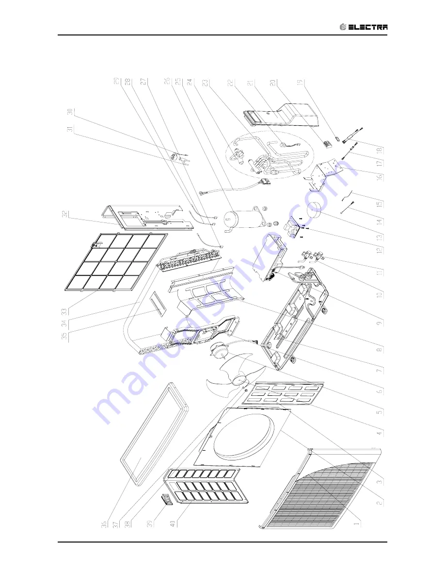
Page 76: ...13 10 EXPLODED VIEWS AND SPARE PARTS LISTS Revision Y05 02 Service Manual Delta DCI 13 10 Outdoor Unit DCR 50 DCI...
Page 77: ...et 1 17 453238700 Wire UL1007 16AWG COM 18 453238600 Wire 1015 16 Power Input 19 204107 Cable clip nylon 1 20 4519188 4 poles terminal block 1 21 433229 Value cover 1 22 4522509 4 Way valve coil 1 23...
Page 78: ...14 1 APPENDIX A Revision Y05 01 Service Manual Delta DCI APPENDIX A INSTALLATION AND OPERATION MANUAL OPERATING MANUAL DELTA 22 25 35 50 DCI INSTALLATION MANUAL DELTA 22 25 35 50 DCI...