background image

General Description

Refrigerant Flow Diagrams - MQH 6 /8/10/14/16

Refrigerant Circuit:

1   Compressor
2   4 Way Valve
3   Coil + Fan
4   Main Capillary
5   Bypass Capillary
6   1 Way Drier Filter
7   Liquid Receiver
8   Heat Exchanger
9   Check Valve
10 Accumulator

Hydraulic Circuit:

11   Drain Valve
12   Safety Valve
13   Water Manometer
14   Expansion Tank
15   Pump
16   Air vent


A  High Pressure Switch 
B  Low Pressure Switch 
C  Differential Pressure Switch 
D  High Pressure Sensor

Refrigerant Circuit:

1   Compressor
2   4 Way Valve
3   Coil + Fan
4   Main Capillary
6   1 Way Drier Filter
7   Liquid Receiver
8   Heat Exchanger 
10 Accumulator


Hydraulic Circuit:

11   Drain Valve
12   Safety Valve
13   Water Manometer
14   Expansion Tank
15   Pump
16   Air vent

A  High Pressure Switch 
B  Low Pressure Switch 
C  Differential Pressure Switch
D  High Pressure Sensor

Refrigerant Flow Diagrams - MQH 12/18

English

Summary of Contents for MQH 10T

Page 1: ...Zertifizierungsstelle Organismo Notificado No 0035 Библиотека СОК ...

Page 2: ...I X English ...

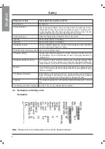
Page 3: ...nit is used at altitude 1000 meter Units is not be used at sites where there is exposure to blast 1 2 Warranty Failure to comply with any of these conditions will automati cally void the warranty 1 3 Emergency stop Normal stop 1 4 An introduction to the manual The emergency stop of the unit can be enabled using the main switch For a normal stop break the relevant connection or press the right side...

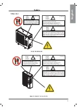
Page 4: ... the presence of any short circuit Inside the heat exchangers the compressors and the refrigeration lines this unit contains liquid and gaseous refrigerant under pressure The release of this refrigerant may be dangerous and cause injuries The units are not designed to be operated with natural refrigerants such as hydrocarbons The manufacturer may not be held liable for any problems deriving from t...

Page 5: ...ention of residual mechanical risks install the unit according to the instructions provided in this manual carry out all the periodical maintenance operations prescribed by this manual do not touch air condensation coils without wearing protec tive gloves do not remove the guards from moving elements while the unit is running check the correct position of the moving elements guards before restarti...

Page 6: ...ry time close the electrical board as soon as the measurement or check has been completed 2 6 Precautions during maintenance operations Maintenance operations can only be carried out by autho rised technicians Before performing any maintenance operations To carry out any measurements or checks which require the activation of the machine for outdoor units do not carry out any operations in the pres...

Page 7: ...trations of R410A must be given medical attention immediately Adequate ventila tion must be provided at all times Recommendations Semiotics or support therapy is recommended Cardiac sensitisation has been observed that in the presence of circulating catecholamines such as adrenalin may cause cardiac arrhythmia and accordingly in case of exposure to high concentrations cardiac arrest Prolonged expo...

Page 8: ... and a respirator Stop the source of the leak if you can do this without danger Negligible leaks can be left evaporating under the sun providing that the room is well venti lated Considerable leaks ventilate the room Reduce the leak with sand earth or other absorbing substances Make sure that the liquid does is not channelled into gutters sewers or pits where the vapours are likely to create a stu...

Page 9: ...is not mandatory but is recommended in case of prolonged exposure to refrigerant oil It is important to wear protective clothing and especially goggles Stop the source of the leak Reduce the leak with absorbing substances sand sawdust or any other absorbing material available on the market Accidental release measures Disposal The refrigerant oil and its waste will be disposed of in an approved inc...

Page 10: ...epurador de malla 60 en la tubería de entrada de unidad Drain all water in the water system during non operating time in winter Vidangez toute l eau du système d eau en hiver quand le système ne fonctionne pas Lassen Sie während der Winterzeit wenn das Gerät außer Betrieb ist alles Wasser aus dem Wassersystem ab Drenare tutta l acqua del sistema idrico durante il periodo di inattività invernoDrene...

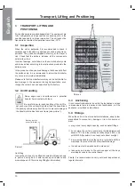
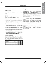
Page 11: ... 2 3 3 Anchoring 3 4 Storage It is not essential to secure the unit to the foundations unless in areas where there is a serious risk of earthquake or if the appliance is installed on steel frame plug or seal every single opening such as water fittings do not store the unit in a room where the temperature will exceed 70 C and the relative humidity exceed 85 unit with R410A if possible do not expose...

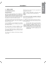
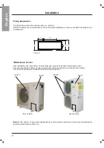
Page 12: ...ow easy access The units should be installed on a flat and hard preferably concrete base Care should be taken at the time of installation to leave enough clearances around the unit for maintenance works When fixing the unit a slope of 1 cm m is recommended to allow draining of rain water For heating mode if the outdoor temperature is likely to fall below 1 C provide a system to prevent the condens...

Page 13: ...ic maintenance works The removal of panel 1 allows access to compressor refrigerant circuit as well as hydronic module The fan motor assembly is accessible after removing the panel 2 panel 2 panel 1 panel 2 panel 1 Remark The panel 1 is removable independently of other panels and allows a start up by maintaining the operating characteristics of the unit English Push to Open w easy access for perio...

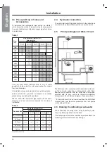
Page 14: ...wner should contact a local water treatment company regarding water treatment However this is critical and care should be taken to make sure it is done properly to prevent problems related to flow A fouled water system will lead to premature component failure Water connections could be damaged by an important stress when screwing them Use a second spanner to compensate the stress of tightening Pro...

Page 15: ...ected with the terminal units such as fan coil units cassettes or wall mounted units Each terminal unit connected with the MQH heat pumps and provided with its own control is therefore completely independent of the chiller see diagram of principle above If the terminal unit is on a lower level than the MQH heat pumps make sure the water pressure in the heat pumps unit is at least 0 5 bar When unit...

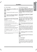
Page 16: ...g connections shall be provided Before connecting the power supply lines check that the available voltage value does not exceed the range specified in the Electric Data Chapter 8 Supplying the unit through a line whose unbalance exceeds the permissible value will automatically void the warranty It s recommended to check the correct sequence of the three supply phases R S T before the unit start up...

Page 17: ...s correct and that fluids have been circulating for at least 4 hours Then clean the filters on the suction side of the pumps Adjust the liquid distribution network in such a way that the flow rate is within the specified range Check that the water quality is up to the specifications Check that oil heaters if any have been turned on at least 4 hours before It is mandatory if the temperature is unde...

Page 18: ...ion at high and low pressure detected by the pressure gauges of the refrigerant are within the following range On the units not provided with HP LP pressure gauges for the refrigerant connect a pressure gauge to the Schreader valves on the refrigeration circuit HP side Approx 13 to 18 C above the temperature of the air entering the condenser for R410A units LP side Approx the difference between th...

Page 19: ...r air temperature sensor short circuited Coil temperature sensor disconnected Outdoor air temperature sensor disconnected Coil temperature sensor short circuited High pressure protection automatic reset for first three times Low pressure limit unit cut out Leaving water temperature below allowed limits Entering water temperature is too high Flow switch opens low water flow CP and EP no change comp...

Page 20: ...ht mode differential Night mode fan change Identification address Display Data Level 1 Level 2 Level 3 UnIt DE PArA Parameters CO or HP Select to show present value Triac output value in from 0 to 100 TO triac output CSPT cooling set point temperature HSPT heating set point temperature tD last deicing duration EWT entering water temperature SEnS Sensor LWT leaving water temperature Select to show ...

Page 21: ...c fan speed controller allows the unit to operate with ambient temperature from 10 to 46 C for MQH06 16 and from 10 to 43 C for MQH18 7 7 Fan 7 6 Air heat exchanger English MQH units are designed for outdoor installation to ensure highly reliable and efficient performance These appliances are fit for medium and small air conditioning applications in the residential and tertiary sectors All the uni...

Page 22: ...on Tank 15 Pump 16 Air vent A High Pressure Switch B Low Pressure Switch C Differential Pressure Switch D High Pressure Sensor Refrigerant Circuit 1 Compressor 2 4 Way Valve 3 Coil Fan 4 Main Capillary 6 1 Way Drier Filter 7 Liquid Receiver 8 Heat Exchanger 10 Accumulator Hydraulic Circuit 11 Drain Valve 12 Safety Valve 13 Water Manometer 14 Expansion Tank 15 Pump 16 Air vent A High Pressure Switc...

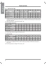
Page 23: ...rt up type Evaporator Number Condenser Hydraulic connections Inlet diameter Outlet diameter Weights Weight of shipment Dimensions Length Width Height 1 Indicative valvue Always refer to the value specified on the unit s label 2 Electric supply tolerance voltage 10 frequency lHz 3 The maximal sound power is lower than 72dB A Inch Inch Direct Plate Coil Femal e 1 80 2 20 2 20 2 84 2 75 102 113 113 1...

Page 24: ...r Plate Direct Number Condenser Coil Hydraulic connections Female Inlet diameter Inch Inch Outlet diameter Weights Weight of shipment Dimensions Length Width Height 1 Indicative value Always refer to the value specified on the unit s label 2 Electric supply tolerance voltage 10 frequency lHz 3 The maximal sound power is lower than 72dB A 3 60 3 53 4 63 5 65 165 182 185 189 English ...

Page 25: ...ssors Compressors MQH Quantity Max absorbed power kW Nominal current A Max current FLA A Max start up current LRA A Crankcass heater W 1 Electric supply tolerance voltage 10 frequency lHz Fans Electrical data Fans MQH Supply voltage V Ph Hz Quantity Rated power per fan kW Total absorbed current FLA A 1 A11 the units are equipped with electric heater for plate heat exchanger anti freeze the input p...

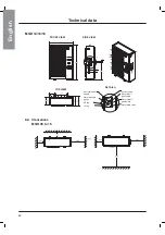
Page 26: ... supply Water inlet 3 4 gas female Water outlet 3 4 gas fcmalc Air vent valve Water drain valve Water drain valve FRONT VIEW MQH 10M 10T 12 SIDE VIEW TOP VIEW DETAIL A Electrical power supply Water pressure gauge HP tap LP tap LP tap HP tap Air vent valve Water inlet 1 gas female Water outlet 1 gas female Water drain valve English ...

Page 27: ...4 16 18 FRONT VIEW SIDE VIEW TOP VIEW DETAIL A Electrical power supply Air vent valve Water outlet 1 gas female Water inlet 1 gas female Water drain valve Water pressure gauge 8 4 Clearences MQH 06 to 18 HP tap LP tap English ...

Page 28: ...ufacturer Unless otherwise specified the operations described below may be carried out only by a trained maintenance operator 9 1 General requirement The units have been designed for continuous operation providing that they are subjected to regular maintenance within the limits specified in this manual Each unit must be serviced according to the programme by the User Customer and must be inspected...

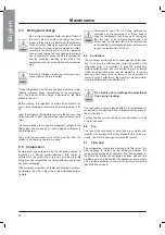
Page 29: ...he plate affixed to the unit Before refilling it is important to drain and de hydrate the circuit thus obtaining a minimum abs pressure value of 50 Pa Inject the refrigerant fluid before removing the vacuum then fill the circuit up to 90 of the total gas requirement in liquid form It is recommended to connect the refrigerant cylinder to the filling valve and to arrange it in such a way as to injec...

Page 30: ... heat exchange the difference between the temperature of the leaving water and the saturated evaporating temperature must be in the 2 4 C range A greater difference would indicate a low efficiency of the heat exchanger i e the heat exchanger is dirty For other maintenance operations extraordinary overhauling replacement of the heat exchanger etc contact an autho rised Service Centre In this case t...

Page 31: ...Anomaly of the oil heater of the compressor s base Check the electric circuit and the resistor of the heater of the motor base and replace defective components Compressors is not working Breaking of the electric circuit ground dispersions and short circuits Check fuses Intervention of the HP pressure switch The fuse of the control circuit is broken Check for ground dispersions and short circuits R...

Page 32: ...eration of the pressure switch replace it if defective The delivery valve is partially closed Open the valve and replace it if faulty Substances with condensable gases in the circuit Drain the circuit The fan of the condenser is stopped Check cables and motor If defective repair of replace The liquid line is too hot Insufficient charge Identify and remove the cause of the loss of charge and refill...

Page 33: ...4 way reversing valve air outlet grill right side plate 1 safety valve partition plate water pump heater exchanger differential pressure swith OAT OCT water inlet temperature water outlet temperature main controller display panel transformer fan motor capacitor phase protector compressor capacitor guard net assembly dry filter LP switch HP transducer HP switch capillary assembly N A N A N A 11 2 O...

Page 34: ...h g i r r e g n a h c x e r e t a e h 2 e t a l p e d i s t h t i r r e t l i f y r d T A O T C O e r u t a r e p m e t t e l n i r e t a w e r u t a r e p m e t t e l t u o r e t a w t h c t i w s e r u s s e r p l a i t n e r e f f i d l e n a p y a l p s i d r e m r o f s n a r t r o t i c a p a c r o t o m n a f y l b m e s s a t e n d r a u g n a f r o t o m n a f e t a l p p o t n o i t p i ...

Page 35: ...les can be discon nected and disassembled Refer to Chapter 4 for the position of connection points Remove all the refrigerant from the refrigeration circuits of the unit and store it in suitable containers using a recovery unit If its characteristics have remained the same the refrigerant can be used again Contact the competent authority to obtain information about disposal In NO event shall the r...

Page 36: ...actory Wired Field Wired Field Wired ITEM MC W MP W MF1 W MF1 A X A Y A FU A QS A WIRE SECTION C01 uF C02 uF MQH06 MQH08M P N C27016000 04 2190 3200 210 210 130 140 50 55 0 43 0 64 8 4 12 2 12 15 8 20 25 25 25 4mm 2 4mm 2 3 3 VALUE ...

Page 37: ...II Appendix A C01 C02 CP C H FS FU K1 MC MP MF1 NIGHT OAT OCT OFF PCB QS R1 R2 RV1 TIN TOUT P N C27016000 04 MQH 06 08M TR HP1 LP1 ...

Page 38: ...III Appendix A Factory Wired Field Wired Field Wired UNIT MQH08T FU 12A 16A QS WIRE SECTION P N C27017000 04 MQH 08T 2 5mm 2 ...

Page 39: ...IV Appendix A C01 CP C H FS FU K1 MC MP MF1 NIGHT OAT OCT OFF PCB QS R1 R2 RV1 TIN TOUT MQH 08T TR HP1 LP1 P N C27017000 04 ...

Page 40: ...V Appendix A MQH 10M Factory Wired Field Wired Field Wired UNIT MQH10M FU 16A 25A QS WIRE SECTION P N C27018000 04 4mm 2 ...

Page 41: ...VI Appendix A C01 C02 C03 CP C H FS FU K1 K2 MC MP MF1 MF2 NIGHT OAT OCT OFF PCB QS R1 R2 RV1 TIN TOUT P N C27018000 04 MQH 10M TR HP1 LP1 ...

Page 42: ...VII Appendix A MQH 10T 12 14 16 18 C27019300 04 Factory Wired Field Wired Field Wired ...

Page 43: ...II Appendix A 1 0 C 2 0 C P C H C S F U F 1 K 2 K C M P M 1 F M 2 F M T H G I N T A O T C O F F O B C P S Q 1 R 2 R 1 V R Z Q S N I T T U O T 4 0 0 0 0 9 1 0 7 2 C N P MQH 10T 12 14 16 18 R T 1 P H 1 P L ...

Page 44: ...IX Appendix B Exploded View MQH 06 08M 08T ...

Page 45: ...X Appendix B MQH 10M 10T 12 14 16 18 ...

Page 46: ......

Page 47: ...Electra Air Conditioning shenzhen Co Ltd 2 Wuhe Avenue S Bantian Buji shenzhen China ...

Reviews: