background image

32

en

8.

Press MEAS to calculate the material velocity and return to the menu screen, or ESC to
cancel.

CALIBRATING TO THE SECOND POINT (ON THE THICK CALIBRATION STANDARD)

1.

Repeat the steps given in section
above, but this time:

Use the 4” calibration standard 
(instead of the 1” calibration stand-
ard)

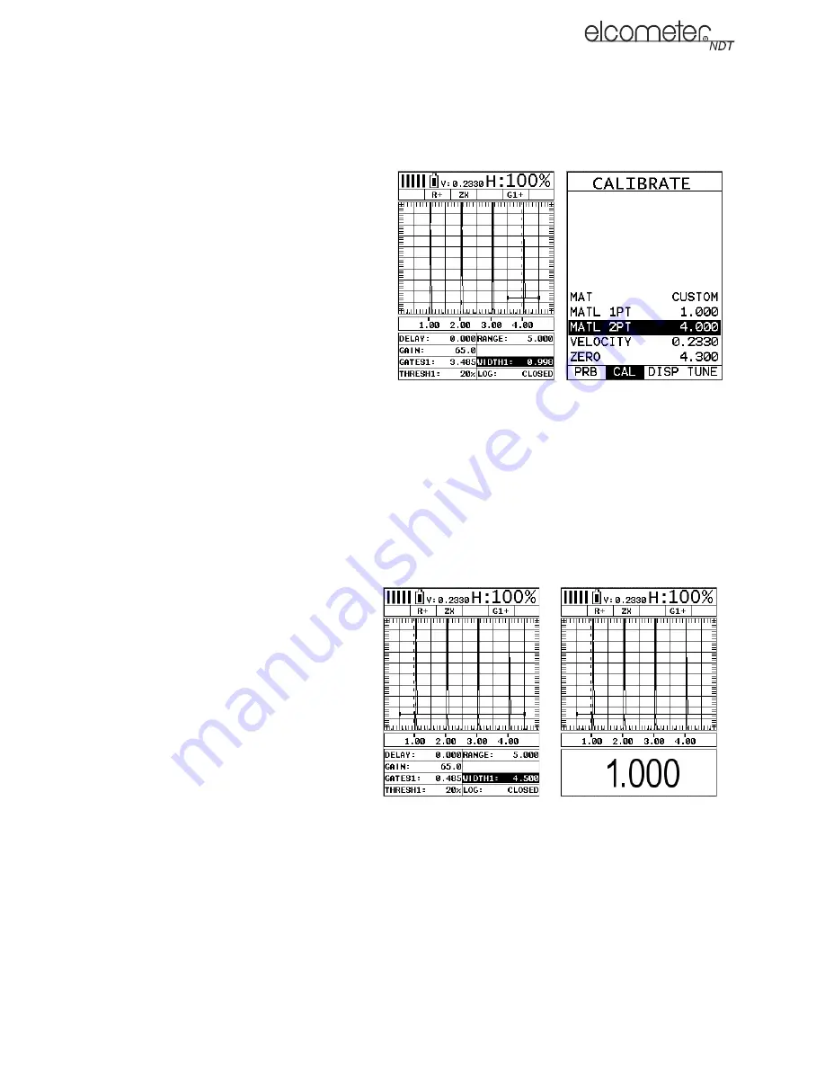
Adjust GATE1 over the waveform - 
as shown in this screenshot.

Adjust the value of MATL 2PT to 
match the length of the 4” calibra-
tion standard (instead of MATL 
1PT).

The material velocity and zero value
are calculated and displayed as
shown.

2.

Press MEAS to return to the measurement screen.

ADJUSTING THE GATE TO THE CALIBRATED RANGE

In order to trigger on anything that is detected in the calibrated range, the boundaries of the gate
must be adjusted to include the entire range.

Note: Caution: in both z-cross & flank detection settings, the first signal to cross the gate will be
triggered on. However, if the peak detection setting has been enabled, the signal with the most
amplitude will be detected.

1.

Press MEAS to view the
measurement screen.

2.

In the hot menu, scroll to GATE1.

3.

Move the gate start to a position
less than 1”.

4.

In the hot menu, scroll to WIDTH1.

5.

Adjust the width of the gate until its
right hand end is at a position
greater than 4”.

6.

Place the transducer back on the
calibration points (1” and/or 4”).

7.

Press OK to display the thickness.

The thickness reading should now
match the known thickness. If the
thickness is not correct, repeat the
calibration procedure.

15.7 CALIBRATION FOR ANGLE BEAM TRANSDUCERS

Further information on Calibration for Angle Beam Transducers can be found on the Elcometer NDT
Knowledge Centre on www.elcometerndt.com.

WIDTH1 adjusted

Press OK to display 

thickness

Summary of Contents for FD700+

Page 1: ...Model FD700DL FD700 Corrosion and Flaw Gauge Operating Instructions...

Page 2: ...cometerndt com The following trademark is a registered trademark of Elcometer Limited Edge Lane Manchester M43 6BU United Kingdom Material Safety Data Sheets for the ultrasonic couplant supplied with...

Page 3: ...15 Setting Up The Flaw Detector 28 16 Measurement Detecting Flaws 33 17 Adjusting the Waveform display 33 18 Gates 35 19 TRIG Trigonometry Mode 36 20 AWS Weld Inspection 38 21 DAC Distance Amplitude C...

Page 4: ...ultrasonic thickness measurement over traditional methods is that ultrasonic measurements can be performed with access to only one side of the material being measured The gauges include a data logging...

Page 5: ...to a computer for analysis and storage To maximise the benefits of your new Elcometer NDT gauge please take some time to read these Operating Instructions Do not hesitate to contact Elcometer NDT or...

Page 6: ...es or disables the Hot Menu If your gauge is displaying a grid log this key toggles an advance to row number option In the MENU MEAS and EDIT functions this key acts as a back or escape function If yo...

Page 7: ...you should have also purchased a suitable transducer for your application If you have not yet done so refer to Transducers For Thickness Measurement on page 25 which will help you identify the correc...

Page 8: ...ons and settings related to taking measurements 5 1 FULL MENU 5 2 HOT KEY MENU Press MENU once to access the menus then press MENU to scroll to the right along the sub menu bar and ESC to scroll left...

Page 9: ...range of display colour schemes You can select one colour scheme from this range 1 Select MENU DISP COLORS 2 Press ENTER to access choose colour screen The Choose Colour screen shows the range of col...

Page 10: ...tect mark To adjust the DETECT MARK setting 1 Select MENU DISP DETECT MARK 2 Use LEFT and RIGHT to locate the type of DETECT MARK 3 Press MEAS to return to the measurement screen 5 5 FRONT PANEL LIGHT...

Page 11: ...DIGITS 6 1 ITEMS COMMON TO ALL MEASUREMENT SCREENS A number of items are common to all the measurement screens A Battery Icon Remaining battery life B Repeatability Stability Indicator This indicator...

Page 12: ...ending on the POLARITY selected The RECT display is the preferred view for flaw and pit inspections D Units The current measurement units Metric English E Feature Status Bar Indicates the features cur...

Page 13: ...e display use one of the following methods to adjust the viewable range of the display When in RF view or RECT view change the values of the DELAY and RANGE functions until the measurement falls insid...

Page 14: ...t enough gain may result in intermittent detection It may also result in lack of detection on internal flaws pits or porosity The gain setting on your gauge can be compared to the volume control of a...

Page 15: ...g the menus 1 Press MENU GT1 THRESHOLD1 THRESHOLD2 and THRESHOLD3 are accessed and adjusted in the same way from the menus for GT2 and GT3 respectively 2 Adjust to suit the measurement application 3 P...

Page 16: ...omatically adjust for temperature changes in the transducer as a result of an increasing decreasing temperature gradient in the test material Note Rough surface conditions can have an effect on the ov...

Page 17: ...NTIFIED PROBE TYPE message press OK to display the predefined list of transducer types by diameter and frequency 2 Using UP or DOWN scroll through the transducer list until the correct type is highlig...

Page 18: ...urements 1 Press MEAS to display the measurement screen 2 Remove all couplant from the face of the transducer and check that the wearface is clean and free of any debris 3 Apply a drop of couplant on...

Page 19: ...ty calibration If the material sound velocity is known this may be entered manually Known Thickness Calibration A sample of the material to be inspected is measured using alternative means and then us...

Page 20: ...ucer and place the transducer in steady contact with the sample or the material being tested Be sure that the reading is stable and the repeatability indicator in the top left corner of the display is...

Page 21: ...Physically measure a location on a coating sample using a set of calipers or a digital micrometer Note The coating sample must be coupled to metal in order to calibrate successfully Place a drop of c...

Page 22: ...second rather than the first echo from the back surface of the material being measured This may result in a thickness reading that is TWICE what it should be Responsibility for proper use of the instr...

Page 23: ...e material The display is updated as each reading is taken 4 Remove transducer from surface The display will show the last measurement made Note Occasionally a small film of couplant will be drawn out...

Page 24: ...s a second This feature enables the user to make scanned passes over an arbitrary length of the test material while still maintaining a reasonable representation of thickness over the scanned area or...

Page 25: ...ive to obtain the best detection results depending on the specific measurement conditions of your application Polarity affects both the gate above or below the x axis in the RF A Scan and the Rectifie...

Page 26: ...better signal quality at various frequencies The damping settings are 50 75 100 300 600 and 1500 ohms The option to adjust the DAMPING setting is found in the MENU TUNE DAMPING 12 9 ATTENUATOR Your g...

Page 27: ...uency negative polarity RECTFW Full Wave Rectified Radio Frequency To see the measurement screen press MEAS To select which measurement screen to use select MEAS DISP VIEW and then select RF RECT RECT...

Page 28: ...rrying out an inspection C Height The signal amplitude height as a percentage of 100 full screen height D Feature Status Bar Indicates the features currently enabled and in use Toolkits TRIG AWS TCG D...

Page 29: ...tch the value of the material you are measuring The zero value must also be set 15 1 TRANSDUCER SETTING TYPE OF The gauge must be set to the correct transducer type SINGLE element or DUAL element 1 Se...

Page 30: ...ple thickness cannot be taken from the material you can choose a material type from a list stored in the gauge For each material stored in the list there is a corresponding longitudinal velocity value...

Page 31: ...bration standards representing the minimum and maximum thickness of the overall inspection range intended are required They must also be of the same material type as the intended application The examp...

Page 32: ...an 1 THRESHOLD 20 POLARITY POSITIVE Note The settings given above are for this particular example calibration You should always use settings which meet the requirements of your applications CALIBRATIN...

Page 33: ...clude the entire range Note Caution in both z cross flank detection settings the first signal to cross the gate will be triggered on However if the peak detection setting has been enabled the signal w...

Page 34: ...play Use the Auto Find function see Auto Find on page 23 This is the preferred method and provides a quick and easy method of adjusting the viewable range Change the values of the DELAY and RANGE func...

Page 35: ...ee DELAY AND RANGE on page 12 17 3 ADJUSTING DELAY AND RANGE Adjusting DELAY and RANGE or B START and B DEPTH on page 13 17 4 GAIN See Section Gain on page 13 17 5 TO ADJUST THE GAIN VALUE To Adjust t...

Page 36: ...ch gate has a start and stop or width a threshold a polarity switch and a detect option Both gates can be enabled and set for different detects and polarities and can be positioned anywhere on the dis...

Page 37: ...ransducer is typically not suitable for inspection As a result a transducer emitting sound at a given angle will allow the operator to position the transducer away from the weld and skip into the weld...

Page 38: ...TRY MODE TRIG MODE SETTINGS ADJUSTING TRIG MODE SETTINGS 1 Select MENU TRIG then the desired function 2 Use the LEFT and RIGHT keys to scroll the value or press ENTER to open the digits edit box and a...

Page 39: ...screen 20 3 USING AWS 1 Couple the transducer to the first calibration standard and peak up on the reflector to achieve maximum signal amplitude 2 Enable the AWS function and adjust the AWS settings t...

Page 40: ...REF GAIN function 9 Use LEFT and RIGHT to scroll the value of SET REF GAIN to OFF 10 Press MEAS to return to the measurement screen 11 Press OK to view the AWS screen 21 DAC DISTANCE AMPLITUDE CORRECT...

Page 41: ...layed 100 is the greatest value that can be displayed DAC All the DAC curve represents 100 Any signal generating an amplitude below the DAC curve is less than 100 and any above greater than 100 Note T...

Page 42: ...ection of the waveform to be used as the first point in the DAC curve and then press ENTER to set the first point of the curve 5 Repeat step 4 multiple times to set other points of the curve The DAC c...

Page 43: ...CG function see Setting up Trigonometry Mode on page 37 TCG SETTINGS ADJUSTING TCG SETTINGS 1 Select MENU TCG 2 Use the LEFT and RIGHT keys to scroll the value or press ENTER to open the digits edit b...

Page 44: ...ess ENTER to set the first point of the curve 5 Repeat step 4 multiple times to set other points of the curve The TCG curve is displayed after three points have been set recorded and will continue to...

Page 45: ...3 Press MEAS to return to the measurement screen ready to begin taking readings 23 2 PULSE WIDTH See Pulse Width on page 24 23 3 PULSER VOLTAGE Your gauge has a 200 V square wave pulser that can be ad...

Page 46: ...wide band option is responsive to all signals within the given frequency range Narrow band filters eliminate signals outside of the target filter frequency and focus on the output of the transducer at...

Page 47: ...ated with each individual reading The identifier can be a combination of up to 10 alphanumeric special characters see below however it must not start or end with a special character Once a start and e...

Page 48: ...ber and a letter where the letter is the column and the number is the row Use TOP LEFT and LOWER RIGHT to define the size of the grid For example a with the TOP LEFT set to A001 and LOWER RIGHT C003 w...

Page 49: ...e gauge is switched off the file will be opened automatically when the gauge is switched on again Press ENTER to display the file from the measurement screen 2 If you want to save the reading to a par...

Page 50: ...eading in this cell location 24 7 EDITING A DATA LOGGER FILE You can edit the following fields of data files Grid files NAME NOTE and INCRement DIRection Sequential files NAME NOTE DIRECTION and LOG S...

Page 51: ...d freely by the user The PC interface software includes a default setup file that can be uploaded to the gauge at any time to restore factory settings However you should consider saving modified setup...

Page 52: ...tion can also be considered an Edit Function 25 3 DELETING A SAVED SETUP This option deletes a setup file from your gauge for example if it is no longer needed 1 Press MENU scroll to the SET menu and...

Page 53: ...de the gauge with the latest version of firmware USB TO SERIAL CONVERTER Some newer laptop computers do not have standard serial ports In this case use the USB to Serial converter supplied with the ga...

Page 54: ...ometer NDT supplier or directly to Elcometer NDT The warranty will be invalidated if the instrument has been opened 28 2 TRANSDUCER The transducer will wear with repeated use Transducer life depends o...

Page 55: ...ing batteries 380 g 13 5 oz Dimensions W x H x D 63 5 mm x 165 mm x 31 5 mm 2 5 x 6 5 x 1 24 Gauge Operating Temperature 10 C to 60 C 14 F to 140 F Case Aluminium case design with gasket sealed end ca...

Page 56: ...u may also have other rights which may vary from country to country state to state or province to province 30 2 OBTAINING SERVICE DURING WARRANTY PERIOD If your hardware should fail during the warrant...

Page 57: ...t com Description Sales Part No Calibration Block 8 Step 1 8mm TW 24005 Calibration Block 10 Step 2 20mm TW 24006 Calibration Block 10 Step 2 5 25mm TW 24007 Replace with S1018 1018 Steel Block A Alum...

Page 58: ...5232 0 206 PVC 2388 0 094 Copper 4674 0 184 Quartz Glass 5639 0 222 Epoxy Resin 2540 0 100 Approx Rubber Vulcanised 2311 0 091 German Silver 4750 0 187 Silver 3607 0 142 Glass Crown 5664 0 223 Steel...

Page 59: ...use with single element angle beam transducers and used as a general prove up flaw inspection mode CAL CALIBRA TION MAT Select the material velocity from a chart of basic material types when a known s...

Page 60: ...oggle between Metric millimetres or English inches units BRIGHTNESS Adjusts the brightness of the display Scale is 0 20 where 20 is the brightest COLORS Choose the display colour scheme from a choice...

Page 61: ...ue of the gain setting GAIN Increases or decreases the overall amplitude of the signal Gain is similar to the volume control on a stereo receiver AGC When operating in E E or E EV mode the gauge adjus...

Page 62: ...you have modified or created DELETE Delete specific setups previously saved in memory DEFAULT SETUP Loads a basic default setup Use only as a last resort if the setups in your gauge have been corrupte...

Page 63: ...if ference from this nominal value GAUGE Set gauge type THICKNESS GAUGE FLAW DETECTOR or REQUEST When set to REQUEST the gauge will ask which mode is required whenever it is switched on XFER TRANSFER...

Page 64: ...re optimise transducer performance PULSER VOLT Provides a 50 V cut boost to the pulser The standard setting is 150 V Provides greater penetration for difficult material types or increased resolution o...

Page 65: ...y dimming the display after idle for a specific amount of time OFF 30 60 90 120 seconds Pressing any key will restore the screen brightness RECT WAVE Toggles between an outlined or filled view option...

Page 66: ...will not display an amplitude percentage of full screen height GT2 Gate 2 The GT2 functions are the same as those for GT1 TRIG Trigonometry TRIG Toggles trigonometry function ON or OFF This function i...

Page 67: ...een height DAC Distance Ampli tude Correction DAC Toggles DAC function ON OFF or AUDIBLE A Distance Amplitude Correction DAC curve is used to configure a variable threshold for the gate using the same...

Page 68: ...LETE ONE FILE Deletes a selected grid or sequential log file from mem ory DELETE ALL DATA Deletes all files currently stored in memory UTIL UTILITIES AUTO FIND Automatically locates the detection poin...

Reviews: