background image


Installatio

In  order  to  safeguard  the  safety  and  safety  of  the  operator  and  the  correct  functioning  of  the 
device,  the  SMSB121TH  device  must  be  installed  only  and  exclusively  by  a  qualified  person.  The 
following standards must also be observed. 

Safety information  


The SMSB121TH incorporates a low power radio transceiver. When in operation by road and receives 
radio frequency energy. Operation in the vicinity of radios, televisions, telephones or elec-
tronic devices in general may cause interference. It may also be subject to interference that 
may affect its performance. 


Do  not  install  the  SMSB121TH  near  pacemakers,  prostheses  or  medial  equipment  in  general,  as 
interference with proper operation of these devices may occur. 


SMSB121TH shall not be installed on board aircraft. 


Do not install the SMSB121TH in the presence of flammable gases or fumes. 


The  SMSB121TH  operates  using  a  radio  signal:  no  mobile  operator  can  provide  a  connection  at 
any time. 

Environmental conditions 

he SMSB121TH device (the device and all the cables connected to it) must be installed in places 
without, or away from, the device: 


Dust, humidity, high heat; 


Direct exposure to sunlight; 


Objects radiating heat; 


Objects producing a strong electromagnetic field; 


Liquids or corrosive chemicals. 


The  SMSB121TH  has  been  designed  to  work  at  a  temperature  between  -5°C  and  +45°C  (standard 
operating temperature). 


Avoid any rapid change in temperature and/or humidity. 

Degree of protection 

When installing the SMSB121TH device, the following degree of protection must be ensured: 


IP40: minimum degree of protection, must always be guaranteed; 


IP54: degree of protection to be provided for use in outdoor applications. 

Power supply 

Observe the following standards: 


Do not use cables longer than 2.9m; 


The external power supply unit must be class 2 (LPS) certified SMPS (not included) 


Do not reverse the polarity of the power supply cables. 

Digital and analog input

Observe the following standards


Connect only clean contact switches, switches and contactors. 


if analog only suitable and certified sensors should be connected; 


Do not use cables longer than 2.9m; 


Do not connect inputs to power sources. 


Do not reverse the polarity of cables in analog inputs

.


Relay output

s


Refer to the chapter on nameplate data. 


Do not use cables longer than 2.9m; 


Connect only one voltage level for all relays: If the load is subjected to pe-recycle voltage, 
use only the phase cable. 


Summary of Contents for smartButler SMSB121TH

Page 1: ......

Page 2: ...2 SMSB121TH V1 0 05 12 2017 ...

Page 3: ...Status GSM 3G 10 Sensors 11 Digital inputs 11 Contact type 11 Alarm Event 11 Analog input 11 Probe type 11 Measure unit 11 Probe maximum value 11 This is the minimum value that the probe can reach 11 Threshold alarms 11 Relay output 13 Response Message 13 Telephone call 13 Power supply failure 13 Periodic status message 14 Users list 14 Log 14 Settings 15 Wi Fi 15 Access Point AP Mode 15 Station M...

Page 4: ...imits of the weather conditions as described in the operating and maintenance man ual It is the customer s responsibility to verify that the product is in fact compatible from a regulatory point of view with the final installation The User must note that the management by remote control is a free choice for which he is solely responsible The use of the product is not permitted for other purposes s...

Page 5: ...torage for purposes other than the user s personal use is prohibited except in the case of specific written consent from Elbro The use copying modification disassembly or transmission of the software is prohibited except as specifically authorized by this license All rights not expressly authorised are reserved to Elbro AG and or its suppliers Any other trademark or pro decret cited refers to its ...

Page 6: ...ce Dust humidity high heat Direct exposure to sunlight Objects radiating heat Objects producing a strong electromagnetic field Liquids or corrosive chemicals The SMSB121TH has been designed to work at a temperature between 5 C and 45 C standard operating temperature Avoid any rapid change in temperature and or humidity Degree of protection When installing the SMSB121TH device the following degree ...

Page 7: ...G Red 50ms off 50ms Red 50ms off 2s Registered 3G Red 100ms off 100ms Red 100ms off 2s Roaming Red 50ms off 50ms Red 50ms off 100ms Roaming 3G Red On fixed Voice call or startup 3 SIM CARD holder Micro SIM CARD compatible Push push type 4 Ignition switches Switches on and off the device see section Start up 5 Analog Sensor Switches Permits sensor configuration see section Ana log input 6 Switch re...

Page 8: ...clean contact and following the regulations in force Connecting relay outputs The installation regulations must be strictly observed referring to the nameplate data see relevant chapter The maximum relay load is 5A 250V 2A 30V Do not exceed the specified limits 0 10V 0 10V 24V G N D S1 S2 probe transmitter AN1 1 2 3 4 5 ON ON 0 20mA LO O P S1 S2 transmitter LO O P probe AN1 S1 S2 probe 1 2 3 4 5 O...

Page 9: ...t with the contacts facing downwards see figure If you choose to use a prepaid SIM Card the SMSB121TH has a credit check function we recommend that you activate it to keep the remaining credit under control Start up Before turning on the device make sure that you have made the wiring and fastened the support base to the wall and insert the SIM card into the special compartment Ignition To turn on ...

Page 10: ... smartbutler is a versatile device with many features to meet in countless applications Thanks to the integrated relay any electrical de vice can be remotely activated with a simple SMS Equipped with two digital and one analog inputs SMSB12TH is able to warn Ada for equipment and systems that require remote supervision With its innovative web interface SMB121TH is able to connect to all modern dev...

Page 11: ... of which allows you to send users an SMS both when opening and clos ing the contact The text of each event can be cus tomized it is also possible to delay the event in order to avoid false alarms Contact type You can set the type of contact you use in the in stallation Dry contact to generate an alarm connect to a potential free contact e g a switch and short circuit it to ground GND Wet contact ...

Page 12: ...12 ...

Page 13: ...ting the system to which it is connected This function can be configured in the following ways Exchange the simple relay exchange ON OFF is carried out Pulse A programmable pulse of 1 65535 seconds is performed The user also has the option of activating the SMS reply option which allows an SMS confirming the command Power supply failure This feature allows selected users to receive a notification ...

Page 14: ...y daily weekly or monthly This mode is useful for monitoring a sys tem or for preventing SIM cards from expiring Switzerland Users list This list contains the telephone numbers of users up to 1000 authorized to receive alarm messages and SMS and email notification Log The log displays the last 50 system events ...

Page 15: ...ted Cellular data The DATA function allows SMSB121TH to send EMAIL through a service provided free of charge by ELBRO AG This service allows the forwarding of emails from the remote control to the emails of the users entered N B See Email service clauses chapter SIM Credit This function allows you to display the remaining credit of the SIM card via USSD command example 130 for the Swisscom network...

Page 16: ...wing table shows a list of SMS commands with their description and example Comando Descrizione Esempio TA 1 4 Activates deactivates the selected temperature alarm 0000 STOP TA1 DA 1 2 Activates deactivates the alarm of the digital input 0000 STOP DA1 AA Activates deactivates the alarm of the analog input 0000 STOP AA PW A 8 30 SMS on off of power failure 0000 STOP PFA PW A0 Activates deactivates S...

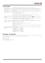
Page 17: ...n 1 Analog Input 0 10V 0 20mA 4 20mA PT100 PT1000 General characteri stics Flammability rating UL94V 0 Degree of protection IP20 Standard operating temperature 15 C to 65 C Indicative weight 93g Maximum conductor cross section that can be inserted in the termi nals 2 5mm2 Absorption typical values Power supply 5 5V Standby 200mA Sending SMS 500mA Switching relays 800mA GPRS UMTS 1500mA Declaration...

Reviews: