background image

N800 

4" Handheld Controller

                                  E L A N   H O M E   S Y S T E M S

Page 56                        © ELAN Home Systems  2007 • All rights reserved.

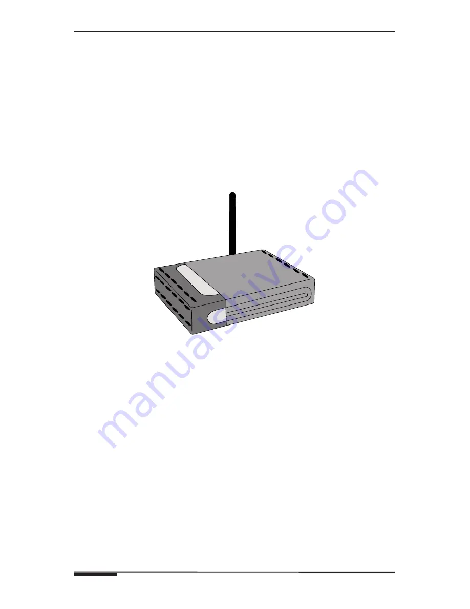
Wireless Access Point

The N800 requires a Wireless Access Point (WAP). The WAP is a device that 
connects the N800 together with the SS1 System Station to create a wireless 
control system. The WAP is connected directly to the router via ethernet, and 
relays data between the N800 and the SS1 System Station. Wireless Routers 
that combine the functions of a Router and WAP are popular options for 
home networks.

NOTE: 802.11b/g standards use the unlicensed 2.4 gigahertz (GHz) 
band. Operating in an unregulated frequency band, 802.11b and 
802.11g equipment can incur interference from microwave ovens, 
cordless phones, and other appliances using the same 2.4 GHz band.

Figure C.3: Wireless Access Point

Wireless Setup

It is essential that a functioning wireless network is set up and functioning 
prior to installing the N800. The Router needs to be configured for 

DHCP 

so 

that it provides IP addresses automatically for each component in the sys-
tem. In order to access the N800’s Internet Browser, the wireless network 
must be configured to access the Internet.

Detailed instructions on wireless network setup are outside the parameters of 
this manual. Please consult the documentation that accompanies the Router 
and/or WAP for specific instructions. 

Summary of Contents for N800

Page 1: ...www elanhomesystems com...

Page 2: ......

Page 3: ...n close proximity to receiving equipment The FCC or Industry Canada can require you to stop using your device if such interference cannot be eliminated If you require assistance contact your local ser...

Page 4: ...ere blasting is in progress Use Sensibly Use only in the normal position as explained in the product documentation Qualified Service Only qualified personnel may repair this product Enhancements and B...

Page 5: ...damage electronic circuit boards Do not attempt to open the device other than as instructed in this guide Do not drop knock or shake the device Rough handling can break internal circuit boards and fin...

Page 6: ...tures 5 Quick Reference 6 Callouts 7 2 System Design Applications 10 Pre Wire 11 Applications 12 3 Connections 17 System Interface Connections 18 4 Operation Setup 21 Device Control 22 System Setup 24...

Page 7: ...lor LCD Liquid Crystal Display screen Depressing the polyester film with the included stylus allows the film to touch the glass panel underneath generating a location signal that is read by the electr...

Page 8: ...E S Y S T E M S Page 6 ELAN Home Systems 2007 All rights reserved N800 Quick Reference Card The N800 is packaged with a Quick reference Card to allow users to quickly access all of the features of the...

Page 9: ...N800 4 Handheld Controller Handheld Controller Callout 1 2 3 4 5 Figure 1 2 N800 Callout Item Item Description 1 Web Cam Not Used 2 Integrated Desk Stand Allows support for tabletop use 3 Speakers Pro...

Page 10: ...er in the respective direction Press the center of the scroll key to activate the highlighted item and to accept confirmation notes ELAN System Control Top and bottom key press controls System Volume...

Page 11: ...owser Application A short keypress changes the zoom level of the current view and adjust the volume up in audio applications 4 Power A short keypress opens the Device Mode dialog A long key press turn...

Page 12: ...pment locations etc Make sure that all loca tions are decided upon before pre wiring commences so that all necessary wiring and installation hardware is in place This unit will be interfacing with oth...

Page 13: ...s Use Cat 5 cable to connect the WAP to the router Router A Router wired or wireless is the heart of the N800 s communication system Location of a wired router is not critical as long as access is pro...

Page 14: ...l One Way RS 232 Controlled Devices x4 ETHERNET RS 232 HOST RS 232 ELAN RS 232 HOST ELAN COM 1 COM 3 COM 2 COM 4 COM1 COM2 COM3 COM4 ETHERNET LINK RX TX IR LINK SENSE INPUTS 1 2 3 4 5 6 ALL IR OUTPUT...

Page 15: ...LOCAL 3 ZONE LOCAL 4 ZONE 4 LOCAL 5 ZONE LOCAL 6 ZONE 6 LOCAL 8 LOCAL 8 ZONE 7 LOCAL 7 ZONE VIA POWER 16VDC 10A 16VDC 4A VIA NET TO SENSE INPUTS USE STEREO 3 5mm PLUGS ONLY EXT IR ANTENNA S 12 VIA Ne...

Page 16: ...LAY 3 RELAY 4 RELAY 5 RELAY 6 RELAY 7 RELAY 8 VIA NET Ol Relay Gate Relay Controlled Devices x8 AUDIO SENSOR CONTACT SENSOR LED LIGHT SENSOR Router Screen Lift Drapes IR Emitter IR Emitter IR Emitter...

Page 17: ...RELAY 7 RELAY 8 VIA NET Ol Relay Gate Relay Controlled Devices x8 AUDIO SENSOR CONTACT SENSOR LED LIGHT SENSOR Router Screen Lift Drapes IR Emitter IR Emitter IR Emitter ZONE SS1 Wireless Access Point...

Page 18: ...SS1 Wireless Access Point VIA dvdj ELANSENSE Sensors Relay Controlled Devices x8 Home Theater Components IR Outputs x12 Sense Inputs x6 Local One Way RS 232 Controlled Devices x4 ETHERNET RS 232 HOST...

Page 19: ...will operate for approximately three hours of continu ous use on a charge ten days in Standby mode The charger port is located on the right side of the panel as shown in Figure 3 1 Figure 3 1 Power Co...

Page 20: ...MADE IN CHINA MODEL VIA2SS1 WARNING DO NOT REMOVE COVER NO USER SERVICEABLE PARTS INSIDE REFER SERVICE TO ELAN APPROVED SERVICE TECHNICIAN Figure 3 4 SS1 System Station System Types The VIA SS1 Syste...

Page 21: ...ti Room Controller based system ZONE applications can provide IR routing in order to control local IR sources IR zone control IR control of system wide sourc es one and two way control of RS 232 devic...

Page 22: ...5 N C 12V G N C INT EXT EXT INT N C IR 485 485 N C 12V G N C Z2C 12V OL ZPAD N C IR 485 485 G V G V Z2B 16V 12V VIA OL N C IR 485 485 G 16V G 16V Z2A 16V VIA OL S6 S12 ZNET S8 6 S12 8 VNET INT EXT INT...

Page 23: ...ylus to operate the touch screen The stylus for the N800 touch screen is located in the upper right corner of the panel and slides out from the chassis easily Figure 4 1 N800 Side View Control Surface...

Page 24: ...n Multiple Selection To select consecutive items place the stylus on a non highlighted item and drag the stylus over the items To add more items place the stylus on a non high lighted item and drag th...

Page 25: ...n handwriting recognition mode the last lowercase character switches to uppercase and vice versa 4 Input Menu key Opens the Text Input Menu which includes com mands such as Edit Copy Cut and Paste 5 S...

Page 26: ...must be in place and in range of the N800 See Appendix C Wireless Networking for greater deatils of wireless network setup and equipment There are two areas in which settings may be adjusted Shortcuts...

Page 27: ...the words Display Settings in this window opens the Display menu as shown in Figure 4 7 Figure 4 7 Display Menu This menu includes Brightness Period Dims the screen after a period of inactivity Switch...

Page 28: ...ound Settings Tapping the word Sound Settings in this window will display the Sounds menu which has two tabs First is the General tab which contains the Master Volume control with a ramping indicator...

Page 29: ...allows the panel to disconnect and change network connections Figure 4 10 Network Connectivity Figure 4 11 Change Connection Menu Select Disconnect and a pop up window will ask if you wish to disconn...

Page 30: ...m this window Select the Home navigation button to return to the VIA Control screen Figure 4 12 Battery Level Indicator Control Panel About While in ELAN mode showing the system control screen select...

Page 31: ...ame Type and IP Address Figure 4 14 Control Panel ELAN Devices Settings The Settings button brings up the Settings page The following choices are available Screen Calibration Date and Time Display Con...

Page 32: ...u in the Home View and using the Scroll key to navigate withinin the menu The calibration sequence consists of touching and holding the screen in four different places Use the stylus and tap where ind...

Page 33: ...Home Systems 2007 All rights reserved Page 31 ELAN HO ME S YST E M S N800 4 Handheld Controller Figure 4 18 Date and Time Date Figure 4 19 Date and Time Time Figure 4 20 Date and Time Daylight Savings...

Page 34: ...the functions Brightness Brightness Period Switch Off Display timeout Lock Screen and Keys and Show LED Lights Figure 4 21 Control Panel Display Select Display to change the display settings The Brigh...

Page 35: ...s in order to save power Switch Off Display determines the time out period that the the display is illuminated after the last touch Choose between 10 seconds 30 seconds 1 minute 2 minutes and 5 minute...

Page 36: ...on the front of the device Press OK to save the settings Figure 4 25 Display Show LED Lights Connectivity Select Connectivity to edit and create Internet connections and to adjust creation logic This...

Page 37: ...tion with ELAN s SS1 System Station and the Internet Connect Automically Select WLAN Connections Figure 4 27 Connectivity Connect Automatically Select Connection Connections that have been saved in th...

Page 38: ...n to be edited Select WLAN then Network Name name of WAP Network Mode infra structure then Security Method None WEP WPA Pre Shared key WPA with EAP These settings will vary depending on the structure...

Page 39: ...ctivity WEP Key Advanced To set Advanced functions Select Advanced button Proxies not typically used IP Address Set N800 to static IP address not recommended Other Transmission Power 100mw default pro...

Page 40: ...vity Advanced Settings To set a static IP address Select the IP Addreses Tab uncheck the Auto Retrieve IP Address box then fill in the appropriate information Figure 4 34 Advanced Settings IP Addresse...

Page 41: ...if the connection is not used Use WLAN Idle Time for connections created through a WLAN access point Figure 4 36 Advanced Settings Idle Time NOTE The network may also have idle timers that may cause...

Page 42: ...ights reserved Language and Region Tapping this button selects the Region and Device Language Figure 4 36 Control Panel Language and Region Figure 4 37 Control Panel Device Language Sounds The Sounds...

Page 43: ...The Download screen will then be displayed as shown in Figure 4 39 Figure 4 39 Control Panel Installer Note This section assumes that a wireless home network is installed and working correctly In orde...

Page 44: ...N800 s Enable button under Download Timeout Press the Download Enable Button on the SS1 IR LINK SENSE INPUTS 1 2 3 4 5 6 Download Enable Button SS1 Figure 4 40 SS1 Download Enable Button In VIA TOOLS...

Page 45: ...VIA TOOLS Scan Page The scanning process will display the SS1 and the N800 in the Transfer Page list Ensure that the Transfer to Device checkbox is checked for both the N800 and the SS1 Figure 4 43 V...

Page 46: ...Home Systems 2007 All rights reserved Customer Data Select the Customer Data button Figure 4 44 Customer Data Enter relevent information using the on screen keyboard Select OK Select Access Point To...

Page 47: ...drop down menu Figure 4 46 Select Access Point Press OK VIA dj To set a static IP address for a VIA dj Digital Music Server Press Set ViaDj Address Touch the text box area with the stylus The Virtual...

Page 48: ...l automatically connect to the Internet and download any available updates A verification screen will be displayed once the update is complete that will indi cate various information including softwar...

Page 49: ...wser Tap the Globe icon and select Open new browser window or Manage bookmarks as shown in Figure 4 49 Figure 4 50 Web Browser Open and Browse Web Pages To open a web page Tap the Address field at the...

Page 50: ...zoom level from the application menu select Web View Zoom and the desired zoom level To view the web page in full screen size Press the Full Screen hard key on the top left of the unit chassis To ret...

Page 51: ...ders are shown on the left and the bookmarks in the selected folder on the right To open a folder and a bookmark contained in it Tap the folder and tap the bookmark twice E Mail To send and receive e...

Page 52: ...n for example when you carry a spare battery in your pocket or purse Short circuiting the terminals may damage the bat tery or the connecting object Leaving the battery in hot or cold places such as i...

Page 53: ...or dealer for assistance Your authorized Nokia service point or dealer will inspect the battery for authenticity If authenticity cannot be verified return the battery to the place of purchase If you...

Page 54: ...S Y S T E M S Page 52 ELAN Home Systems 2007 All rights reserved Remove the battery from the right edge of the unit by prying up with thumbnail Replace the battery as shown in Figure 4 53 Replace the...

Page 55: ...ENABLE BUTTON on SS1 3 Incorrect VIA TOOLS download procedure carefully follow download steps in this manual and in VIA TOOLS Help file N800 won t control devic es zones etc 1 Router locked up Reset...

Page 56: ...ammed with ELAN VIA TOOLS Setup Software PC Wireless Touch Panel N800 ZONE SYSTEM SS1 HOST RS 232 ELAN RS 232 HOST ELAN COM 1 COM 3 COM 2 COM 4 COM1 COM2 COM3 COM4 ETHERNET LINK RX TX IR LINK SENSE IN...

Page 57: ...t the SS1 Installation Manual SENSE INPUTS ELAN RS 232 ALL IR OUTPUT EXT IR INPUT IR OUTPUTS 1 7 2 8 3 9 4 10 5 11 6 12 IR PWR VIA NET SS1 POWER 12VDC 0 5 AMPS HOST ELAN COM3 COM4 ETHERNET COM1 COM2 C...

Page 58: ...Hz band Operating in an unregulated frequency band 802 11b and 802 11g equipment can incur interference from microwave ovens cordless phones and other appliances using the same 2 4 GHz band Figure C 3...

Page 59: ......

Page 60: ...ipment sold by but not manufactured by ELAN the warranty obligations of ELAN shall in all respects conform to the warranty actually extended to ELAN by its supplier The foregoing warranties do not cov...

Reviews: