background image

7

contact

   [email protected]

  EL-IP-OTF2-WH 

/

 EL-IP-OTF2-BK 

/

 EL-IP-OTA4-WH 

/

 EL-IP-OTA4-BK

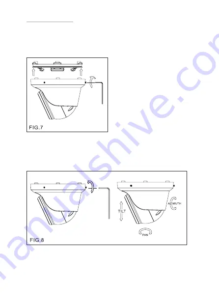
3. Secure the upper cover to the bottom bracket with a hex key FIG.7).

4. Adjust the pan, tilt, and azimuth of the camera to the desired location 

(FIG.8). After the adjustment, tighten the screws to complete the 
installation.

Make sure the light sensor is at the lowest side of the camera (FIG.1). 

Summary of Contents for EL-IP-OTF2-WH

Page 1: ...EL IP OTF2 WH EL IP OTF2 BK EL IP OTA4 WH EL IP OTA4 BK Quick Start Guide ...

Page 2: ...illance Integration Notes for setup and software configuration ELAN Integration Notes are served through the ELAN tools and on elanhomesystems com dealer resources The software configuration information in this document can be used to extend device control parameters for use within an ELAN controller environment or be used to operate this hardware independent of an ELAN controller NOTES ...

Page 3: ...ever there is no guarantee that interference will not occur in a particular installation If this equipment does cause harmful interference to radio or television reception which can be determined by turning the equipment off and on the user is encouraged to try to correct the interference by one or more of the following measures Reorient or relocate the receiving antenna Increase the separation be...

Page 4: ...er cover 2 Lens 3 Infrared LED IR LED 4 Light sensor 5 RJ 45 Ethernet connector supports PoE 6 Power jack DC12V 10 7 Reset Wire strip off the wire insulation if needed after the camera is reset cut off the bare wire PART DESCRIPTION DIMENSIONS Unit mm ...

Page 5: ...P OTF2 BK EL IP OTA4 WH EL IP OTA4 BK 1 Retrieve the camera and remove the bottom bracket from the upper cover with a hex key FIG 1 Use the included screws M4 0x25 through the holes marked as a and fix the camera in the desired location FIG 2 FIG 3 INSTALLATION ...

Page 6: ...ectively FIG 4 Connect the RJ 45 Ethernet cable with a waterproof connector First remove the waterproof connector and unscrew the waterproof nut Insert the Ethernet cable and connect to the RJ 45 connector with proper tools FIG 5 Then tighten the waterproof connector and nut before the RJ 45 connector is connected to the camera FIG 6 ...

Page 7: ...OTA4 BK 3 Secure the upper cover to the bottom bracket with a hex key FIG 7 4 Adjust the pan tilt and azimuth of the camera to the desired location FIG 8 After the adjustment tighten the screws to complete the installation Make sure the light sensor is at the lowest side of the camera FIG 1 ...

Page 8: ...lease follow one of the system architectures 1 Use DC12V power adapter and network switch connected to a network 3 Use PoE power injector and the network switch connected to the network SYSTEM CONNECTIONS 2 Use with PoE of the network switch connected to the network EL IP OT EL IP OT EL IP OT PoE PoE ...

Page 9: ...at can access the IP camera Administrator is authorized to reset basic mode settings and see live video while the guest is only allowed to see live video The default usernames and passwords are as follows To log on to the IP camera please enter the username and password on the login page and click Submit to enter the system Once complete you can access the IP camera s live video by entering the de...

Page 10: ...tion system please refer to the integration note at the beginning and use the ELAN configurator for Auto Discover Auto Configure features If installing camera with no ELAN system follow the browser connections below Before accessing the IP camera make sure that the camera s RJ 45 network audio and power cables are properly connected To set the IP address consult your network administrator for an a...

Page 11: ...leasing 2 The camera will be restored to factory default settings after approximately 90 seconds and will reboot automatically 3 Search for the IP device 4 Start the IP device via an Internet browser 5 Enter the default username ELAN and password 3526 to operate NOTE Cameras are configured to use DHCP by default but will revert to the default address 192 168 0 200 if a DHCP server is not available...

Page 12: ...2 5555 US 1 707 283 5900 International 1 707 283 5901 Fax tech support techsupport elanhomesystems com web elanhomesystems com ELAN is a registered trademark of Nortek Security Control LLC All rights reserved 2019 Nortek Security Control ...

Reviews: