background image


eSE  Series 


Pad Diagrams (V1.1) 01.17.2005


 7 

(These diagrams are subject to change without further notice)


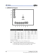
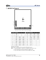
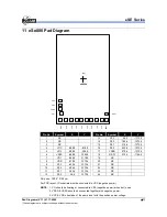
7 eSE020 Pad Diagram 

VO2

VSSC

VO1

(0,0)

eSE020

4

5

6

7

8

9

10

11

12

13

14

P2.
2

P2.
3

P3.
0

P3.
1

P3.
2

P3.
3

VDD

VCC

18

OSCI

15

16

17

VSSD

P2.
0

P2.
1


Pin No. 

Symbol 

Pin No. 

Symbol 

1 NC     

13 P2.3 

66.2 

-718.4 

2 NC     

14 P2.2 

192.6 

-718.4 

3 NC     

15 P2.1 

315.6 

-718.4 

4 VCC 

-588.0 

-163.9  16 P2.0 

442.0 

-718.4 

5 VO2 

-588.0 

-283.9  17 

VSSD 

579.6 

-718.4 

6 VSSC 

-588.0 

-403.9  18 OSCI 

573.4 

-541.5 

7 VO1 

-568.0 

-523.9  19 NC   


8 VDD 

-570.2 

-718.4  20  NC   


9 P3.3 

-432.6 

-718.4  21 NC   


10 P3.2 

-306.2 

-718.4  22  NC   


11 P3.1 

-183.2 

-718.4  23  NC   


12 P3.0 

-56.8 

-718.4  24  NC   


Chip size 

:

 1500 * 1800 

µ

For PCB layout, IC substrate must be connected to VSS (negative power). 

NOTE:

  1. VO should be floating or connected to VSS (negative power) when not in use. 


2. VSSD & VSSC should be connected together with negative power. 


3. VCC & VDD should be of the same level with the positive power voltage. 

Summary of Contents for EASY SOUND eSE Series

Page 1: ...EASY SOUND eSE Series Tiny Controller Based Speech Synthesizer Pad Diagrams Doc Version 1 1 ELAN MICROELECTRONICS CORP January 2005 ...

Page 2: ... of ELAN Microelectronics products in such applications is not supported and prohibited NO PART OF THE EASY SOUND AND OF THIS MANUAL MAY BE REPRODUCED OR TRANSMITTED IN ANY FORM OR BYANY MEANS WITHOUT THE EXPRESS WRITTEN PERMISSION OF ELAN MICROELECTRONICS ELAN MICROELECTRONICS CORPORATION Headquarters No 12 Innovation Road 1 Science based Industrial Park Hsinchu Taiwan R O C 30077 Tel 886 3 563 9...

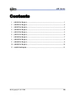
Page 3: ... eSE003 Pad Diagram 1 2 eSE005 Pad Diagram 2 3 eSE007 Pad Diagram 3 4 eSE009 Pad Diagram 4 5 eSE012 Pad Diagram 5 6 eSE015 Pad Diagram 6 7 eSE020 Pad Diagram 7 8 eSE030 Pad Diagram 8 9 eSE040 Pad Diagram 9 10 eSE060 Pad Diagram 10 11 eSe080 Pad Diagram 11 ...

Page 4: ...eSE Series iv Pad Diagrams V1 1 01 17 2005 ...

Page 5: ...2 4 383 4 3 NC 11 P2 0 317 1 383 4 4 NC 12 VSSD 460 0 367 1 5 VCC 458 9 397 9 13 NC 6 VO2 338 9 397 9 14 OSCI 459 0 381 4 7 VSSC 218 9 397 9 15 NC 8 VO1 98 9 377 9 16 NC Chip size 1180 1100 µm For PCB layout IC substrate must be connected to VSS negative power NOTE 1 VO should be floating or connected to VDD positive power when not in use 2 VSSD VSSC should be connected together with negative powe...

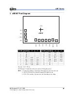
Page 6: ...4 0 399 1 12 VSSD 158 6 354 4 4 VO2 544 0 279 1 13 OSCI 299 0 352 4 5 VSSC 544 0 159 1 14 NC 6 VO1 524 0 39 1 15 NC 7 VDD 489 8 351 1 16 NC 8 P3 3 348 4 354 4 17 NC 9 P3 2 226 9 354 4 18 NC Chip size 1400 1050 µm For PCB layout IC substrate must be connected to VSS negative power NOTE 1 VO should be floating or connected to VDD positive power when not in use 2 VSSD negative power VSSC should be co...

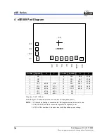
Page 7: ...8 4 3 NC 11 P2 1 221 4 378 4 4 VCC 632 4 27 9 12 P2 0 346 1 378 4 5 VO2 632 4 147 9 13 VSSD 475 8 363 4 6 VSSC 632 4 267 9 14 OSCI 624 8 378 4 7 VO1 612 4 387 9 15 NC 8 VDD 148 0 363 4 16 NC Chip size 1560 1100 µm For PCB layout IC substrate must be connected to VSS negative power NOTE 1 VO should be floating or connected to VSS negative power when not in use 2 VSSD VSSC should be connected togeth...

Page 8: ...8 4 3 NC 11 P2 1 221 4 378 4 4 VCC 632 4 27 9 12 P2 0 346 1 378 4 5 VO2 632 4 147 9 13 VSSD 475 8 363 4 6 VSSC 632 4 267 9 14 OSCI 624 8 378 4 7 VO1 612 4 387 9 15 NC 8 VDD 148 0 363 4 16 NC Chip size 1560 1100 µm For PCB layout IC substrate must be connected to VSS negative power NOTE 1 VO should be floating or connected to VSS negative power when not in use 2 VSSD VSSC should be connected togeth...

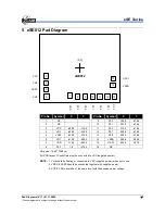
Page 9: ... VCC 630 0 130 9 11 P2 2 375 9 478 4 4 VO2 630 0 250 9 12 P2 1 500 6 478 4 5 VSSC 630 0 370 9 13 P2 0 625 3 478 4 6 VO1 610 0 490 9 14 VSSD 588 4 286 2 7 VDD 118 2 463 4 15 OSCI 603 4 137 2 8 P3 3 1 8 478 4 16 NC Chip size 1540 1290 µm For PCB layout IC substrate must be connected to VSS negative power NOTE 1 VO should be floating or connected to VSS negative power when not in use 2 VSSD VSSC shou...

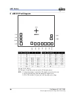
Page 10: ... VCC 630 0 130 9 11 P2 2 375 9 478 4 4 VO2 630 0 250 9 12 P2 1 500 6 478 4 5 VSSC 630 0 370 9 13 P2 0 625 3 478 4 6 VO1 610 0 490 9 14 VSSD 588 4 286 2 7 VDD 118 2 463 4 15 OSCI 603 4 137 2 8 P3 3 1 8 478 4 16 NC Chip size 1540 1290 µm For PCB layout IC substrate must be connected to VSS negative power NOTE 1 VO should be floating or connected to VSS negative power when not in use 2 VSSD VSSC shou...

Page 11: ... 588 0 163 9 16 P2 0 442 0 718 4 5 VO2 588 0 283 9 17 VSSD 579 6 718 4 6 VSSC 588 0 403 9 18 OSCI 573 4 541 5 7 VO1 568 0 523 9 19 NC 8 VDD 570 2 718 4 20 NC 9 P3 3 432 6 718 4 21 NC 10 P3 2 306 2 718 4 22 NC 11 P3 1 183 2 718 4 23 NC 12 P3 0 56 8 718 4 24 NC Chip size 1500 1800 µm For PCB layout IC substrate must be connected to VSS negative power NOTE 1 VO should be floating or connected to VSS ...

Page 12: ... 588 0 163 9 16 P2 0 442 0 718 4 5 VO2 588 0 283 9 17 VSSD 579 6 718 4 6 VSSC 588 0 403 9 18 OSCI 573 4 541 5 7 VO1 568 0 523 9 19 NC 8 VDD 570 2 718 4 20 NC 9 P3 3 432 6 718 4 21 NC 10 P3 2 306 2 718 4 22 NC 11 P3 1 183 2 718 4 23 NC 12 P3 0 56 8 718 4 24 NC Chip size 1500 1800 µm For PCB layout IC substrate must be connected to VSS negative power NOTE 1 VO should be floating or connected to VSS ...

Page 13: ... 588 0 293 9 16 P2 0 442 0 848 4 5 VO2 588 0 413 9 17 VSSD 579 6 848 4 6 VSSC 588 0 533 9 18 OSCI 573 4 671 5 7 VO1 568 0 653 9 19 NC 8 VDD 570 2 848 4 20 NC 9 P3 3 432 6 848 4 21 NC 10 P3 2 306 2 848 4 22 NC 11 P3 1 183 2 848 4 23 NC 12 P3 0 56 8 848 4 24 NC Chip size 1500 2050 µm For PCB layout IC substrate must be connected to VSS negative power NOTE 1 VO should be floating or connected to VSS ...

Page 14: ...C 588 0 558 9 16 P2 0 442 0 113 4 5 VO2 588 0 678 9 17 VSSD 579 6 113 4 6 VSSC 588 0 798 9 18 OSCI 573 4 936 5 7 VO1 568 0 918 9 19 NC 8 VDD 570 2 113 4 20 NC 9 P3 3 432 6 113 4 21 NC 10 P3 2 306 2 113 4 22 NC 11 P3 1 183 2 113 4 23 NC 12 P3 0 56 8 113 4 24 NC Chip size 1500 2600 µm For PCB layout IC substrate must be connected to VSS negative power NOTE 1 VO should be floating or connected to VSS...

Page 15: ...8 0 818 9 16 P2 0 442 0 1373 4 5 VO2 588 0 938 9 17 VSSD 579 6 1373 4 6 VSSC 588 0 1058 9 18 OSCI 573 4 1196 5 7 VO1 568 0 1178 9 19 NC 8 VDD 570 2 1373 4 20 NC 9 P3 3 432 6 1373 4 21 NC 10 P3 2 306 2 1373 4 22 NC 11 P3 1 183 2 1373 4 23 NC 12 P3 0 56 8 1373 4 24 NC Chip size 1500 3100 µm For PCB layout IC substrate must be connected to VSS negative power NOTE 1 VO should be floating or connected ...

Page 16: ...eSE Series 12 Pad Diagrams V1 1 01 17 2005 These diagrams are subject to change without further notice ...

Reviews: