background image


    DK50


08/2014 

 - 5 - 

SM-DK50-EN-1-08-2014-MD


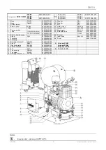
 Fig.1 –   Compressor  


Fig. 2 -   Compressor with membrane dryer  


1. Compressor 

motor 

2. Air 

tank 

3. Check 

valve 

4. Pressure 

switch 

5. Safety 

valve 

6. Manometer 
7. Drain 

valve 

8. Input 

filter 

9. 

Dryer   

10. Pipe 

cooler 

11. Output 

filter 

12. Condenser 

outlet 

13. Solenoid 

valve 

14. Cooler 
15. Check 

valve 


16. 

Magnetic bottle holder 

17. Fan 
18. Micro-filter 
19. Filter 
20. Bottle 
21. Stopper 


15 

Summary of Contents for DK50 2V/110

Page 1: ......

Page 2: ......

Page 3: ...N 2 1 ALERT NOTICES AND SYMBOLS 2 2 MODEL VARIATIONS AND THEIR USES 3 3 TECHNICAL DATA 3 4 FUNCTION 4 INSTALLATION 6 5 WIRING DIAGRAMS 7 6 SWITCHING THE COMPRESSOR ON 8 MAINTENANCE 8 7 MAINTENANCE SCHEDULE 8 8 MAINTENANCE 8 9 SOLVING PROBLEMS 11 LIST OF SPARE PARTS 2 ...

Page 4: ...n Dangerous electric voltage Read the user manual CE mark of compliance Caution Hot surface Compressor is remote controlled and may start without warning Earth ground connection Terminal for ground connection Fuse Alternating current Handling mark on package Fragile handle with care Handling mark on package This way up vertical position of cargo Handling mark on package Protect against moisture Ha...

Page 5: ...over pressure 5 bar Lit min 1 75 75 75 75 Maximal current A 3 4 4 3 8 6 3 4 4 3 8 6 3 4 4 3 8 6 3 4 4 3 8 6 Maximal current of compressor with dryer A 3 6 4 5 8 8 3 6 4 5 8 8 Motor performance kW 0 55 0 55 0 55 0 55 Air tank capacity Lit 5 5 10 10 Pressure range bar 4 5 6 0 4 5 6 0 4 5 6 0 4 5 6 0 Maximum operating pressure of safety valve bar 8 0 8 0 8 0 8 0 Sound level LpfA dB 65 45 65 45 Mode o...

Page 6: ... The dryer provides continuous drying of the compressed air Dry clean compressed air free from oil traces is stored in the air tank ready for use Compressor with condensation and filtration unit Fig 3 The compressor 1 draws in air through a filter 8 and compresses it through a check valve 3 into an air tank 2 The compressed air from the nozzle flows through a cooler 10 that cools the compressed ai...

Page 7: ...mpressor motor 2 Air tank 3 Check valve 4 Pressure switch 5 Safety valve 6 Manometer 7 Drain valve 8 Input filter 9 Dryer 10 Pipe cooler 11 Output filter 12 Condenser outlet 13 Solenoid valve 14 Cooler 15 Check valve 16 Magnetic bottle holder 17 Fan 18 Micro filter 19 Filter 20 Bottle 21 Stopper 15 ...

Page 8: ...n and training of all operators shall be confirmed by the installer s signature on the certificate of installation Prior to installation ensure that the compressor is free of all transport packaging and stabilizers to avoid any risk of damage to the product Caution When in operation the compressor is hot Burns or fire may result if contact is made by the operator or any flammable material 4 1 Plac...

Page 9: ...he output pressure hose drain hose and power cord out the back of the compressor Slide the box over the compressor so that the front face of the box matches the front part of the compressor and the box is fully seated Make sure that the pressure hose drain hose and electric cord come out via the opening at the back of the box Position the drain hose with its valve in the holder at the rear of the ...

Page 10: ...icable national legal regulations A report must be prepared on the results of the tests e g according to EN 62353 Annex G including the measurement methods used Time interval Maintenance that must be performed Chapter Performed by 1 x day Release condensate At high air humidity Compressor without air drier Compressors with air drier Compressors with condensation unit from filter from pressure vess...

Page 11: ...nning the following procedures 8 2 Safety valve check Fig 5 When the compressor is operated for the first time make sure that the safety valve is working properly Turn screw 4 of safety valve 1 several rotations to the left until the safety valve releases air Let the safety valve blow out for only a few seconds Turn screw 4 to the right until it seats closing the valve The safety valve must never ...

Page 12: ... disconnect the appliance from the mains Fig 10 In the case of a regular operation of a condensation unit it is necessary to replace the filter inside the filter with automatic desludging Release a safety lock 1 on the filter vessel by its pulling downwards slightly rotate the filter cover 2 to the left and take it out Unscrew the filter holder 3 by its rotation to the left Replace the filter and ...

Page 13: ...eater volume of condensed liquid in pressure vessel Check pneumatic distribution system seal loose joint Clean valve replace seals replace valve Drain condensed liquid Prolonged running of compressor Air leak in pneumatic distribution system Worn piston ring Contaminated input filter Defective solenoid valve Check pneumatic distribution system seal loose joint Replace worn piston ring Replace cont...

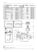
Page 14: ...er 5 3 043000002 000 3 Rubber leg 074000004 000 3 Rubber leg 074000004 000 4 Noise insulatation pad 4KA 134 061000018 000 4 Noise insulatation pad 4KA 532 061000037 000 5 Noise insulatation pad 4KA 136 061000056 000 5 Noise insulatation pad 4KA 534 061000059 000 6 Lower case 2KA 133 023000259 000 6 Lower case 2KA 343 023000258 000 7 Rivet 044000012 000 7 Rivet 044000012 000 8 Noise insulatation pa...

Page 15: ...x5 061000260 000 17 Noise insulatation pad 41 x11 5x3 061000259 000 6 Lower case compl 023001704 000 18 Noise insulatation pad 41 5x3x2 061000254 000 7 Pin 049000154 000 19 Noise insulatation pad 061000258 000 8 Pin spring M4 049000155 000 20 Noise insulatation pad 4KC 256 062000411 000 9 Nut M4 042000002 000 21 Fan tunnel 4KC 143 023000652 000 10 Washer 4 043000003 000 22 Rivet 044000012 000 11 N...

Page 16: ... 024000238 000 21 Nut M8 042000006 000 3 Electric panel 230 50 604021059 000 22 Safety valve 4BA 025 604011025 000 115 60 604021152 000 23 Gasket CU 4KA 078 025900003 000 4 Thermo switch 033510012 000 24 Manometer 50 G 025400003 000 5 Fuse T10A 230 50 60Hz 038100005 000 25 Silencer G 1 8 025400018 000 T 16A 110 50 60Hz 038100007 000 26 Solenoid valve 230 50 036100022 000 6 Electric board housing 6...

Page 17: ...400003 000 6 Fuse T10A 230 50 60Hz 038100005 000 25 Solenoid valve 230 50 036100022 000 T 16A 110 50 60Hz 038100007 000 115 60 036100045 000 7 Electric board housing 604031537 000 26 Silencer 025400018 000 8 Screw D3 2 041000004 000 27 Input hose 4BA 013 604011013 000 9 Fixing lug 033400034 000 28 Dryer 603012169 000 10 Fixing lug 033400018 000 11 Damping element S 4CA 215 604021215 000 12 Screw M...

Page 18: ...r 3KC 417 023000776 000 4a Compressor with dryer 4CA 247 604021247 000 23 Screw M8x25 041000511 000 4b Compressor without dryer 4CA 208 604021208 000 24 Washer 8 IV 043000009 000 5 Spring 022000010 000 25 Nut M8 042000006 000 6 O ring d50x2 073000109 000 26 Membrane screw 4KA 016 1 024000007 000 7 Valve plate 4CA 023 604021023 000 27 Membrane 4KA 031 1 024000008 000 8 Cylinder 4KB 832 050000036 00...

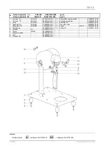
Page 19: ...switch pipe 024000357 000 2 Plug 4KA 953 024000247 000 12 Securing Nut 024000162 000 3 Base plate 5l 3KB 954 023000567 000 13 Non return valve 025300007 000 Base plate 10l 3KB 909 023000534 000 14 Fitting MF3 8 025400034 000 4 Rubber leg 074000010 000 15 Fitting 1 4 024000311 000 5 Washer 5 3 043000101 000 6 Screw M5x25 041000208 000 7 Pressure switch 604031061 000 8 Nut 024000027 000 9 Gasket CU ...

Page 20: ...000208 000 12 Plug 4KA 953 024000247 000 4 Fitting block to press switch 024000101 000 13 Plug 024000844 000 5 Gasket CU 025900004 000 14 Non return valve 025300007 000 6 Nut 024000027 000 15 Fast on coupling 025500247 000 7 Pressure switch pipe 024000357 000 16 Base plate 10l 3KC 116 023000640 000 8 Securing Nut 024000162 000 9 Pressure switch 604031061 000 Notice Bonded joints adhesive LOCTITE 2...

Reviews: