4
Control Bar
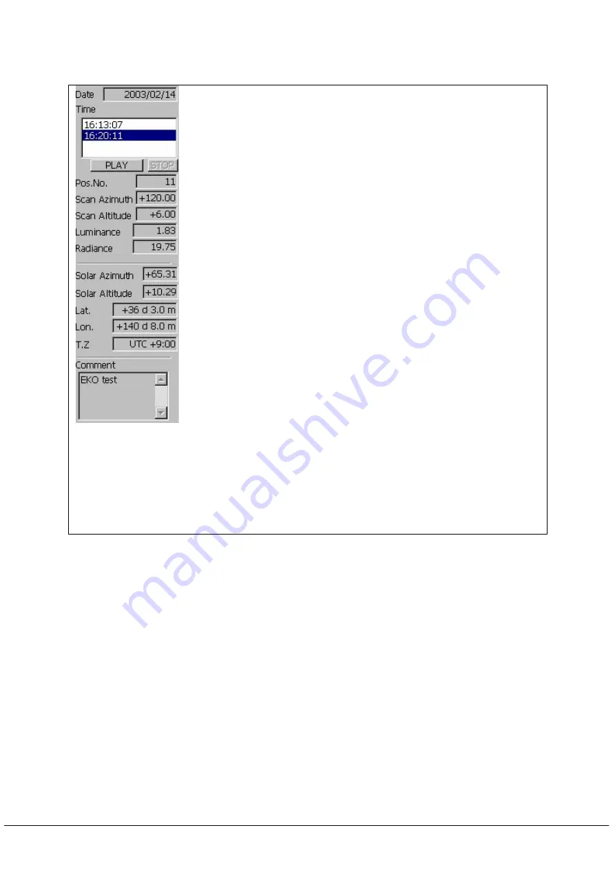
The following control bars are prepared as shown in Figure 5.
①
Date : Measurement date of data displayed on the active windows.
②
Time : Measurement time of data displayed on the active windows.
Time of data displaying the distribution of measurement value
will be displayed in reversed style.
③
PLAY :Data on the active windows will be displayed automatically one by
one per second.
④
STOP :It stops automatic display previously described in
③
.
⑤
Number of position :It displays channel number that shows information
on control bar. By clicking the cell shown in a distributed
display, channel number can be changed.
⑥
Azimuth angle :It displays the azimuth angle of the specified channel
number.
⑦
Altitude angle :It displays the altitude angle of the specified channel
number.
⑧
Luminance :It displays luminance of the specified channel number.
⑨
Radiance :It displays radiance of the specified channel number.
⑩
Solar azimuth angle
:
It displays solar azimuth angle of measurement
time of the data displayed at latitude and longitude of the site.
⑪
Solar altitude angle
:
It displays solar altitude angle of measurement
time of the data displayed at latitude and longitude of the site.
⑫
Latitude :It displays latitude of the site set by measurement setting
dialog.
⑬
Longitude :It displays latitude of the site set by measurement setting
dialog.
⑭
time-zone differences :It displays time-zone differences of system clock
of PC.
⑮
Comment :It displays the comment set by measurement setting dialog.
※
Azimuth angle
:
It can be obtained if we take south as 0
°
, clockwise as
plus and counterclockwise as minus. (-180
°~
+180
°)
※
Altitude angle
:
It can be obtained if we take a horizontal surface as 0
°
and vertical direction as plus.(0
°~
90
°
)
Figure 5. Explanation of control bar
5
Measurement Method
(1) Start the software
Start “SkyScanner.exe”.
(2) Measurement setting
In order to perform measurement setting, select “measurement(0)-setting(P) from
file menu or click
⑫
tool button of the tool bar. Then measurement setting dialog will
open as shown in Figure. 6. You should see List. 4 and input measurement setting.
①
②
③④
⑤
⑥
⑦
⑧
⑨
⑩
⑪
⑫
⑬
⑭
⑮
14


