background image

7. Specifications

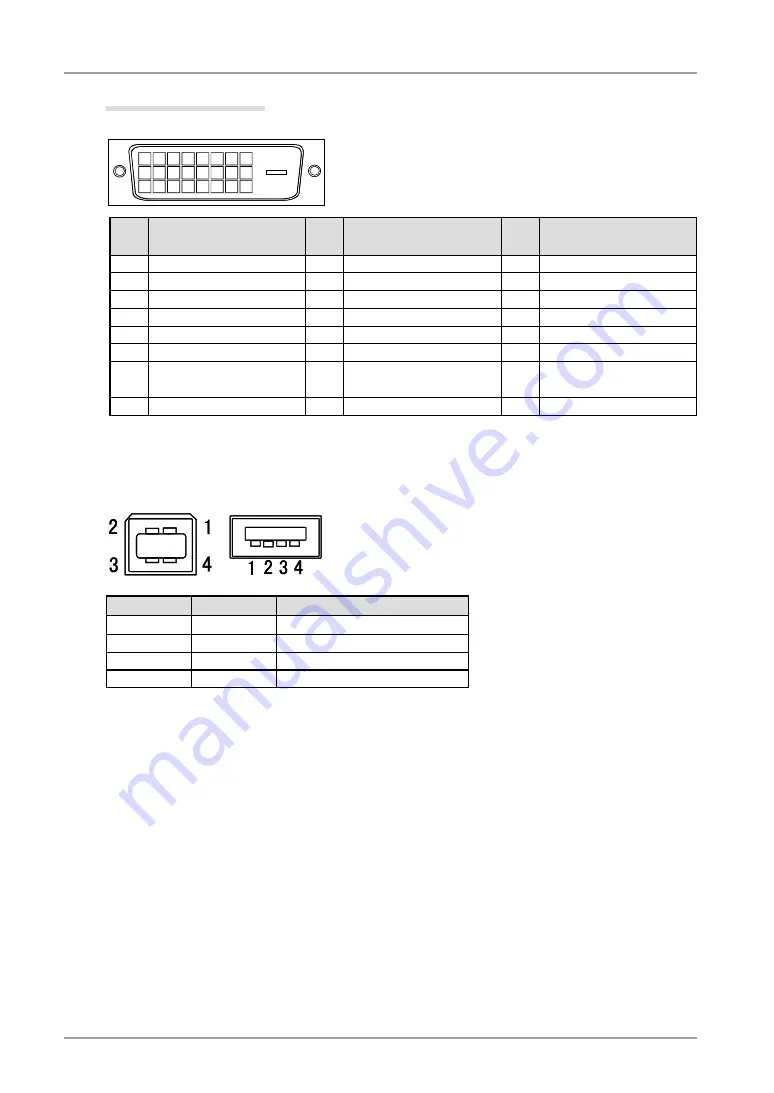
Pin Assignment

•DVI-D Connector

1 2 3 4 5 6 7 8
9

10 11 12 13 14 15 16

19 20 21

17 18

22 23 24

Pin 

No

Signal

Pin 

No

Signal

Pin 

No

Signal

1

T.M.D.S. Data2-

9

T.M.D.S. Data1-

17 T.M.D.S. Data0-

2

T.M.D.S. Data2+

10 T.M.D.S. Data1+

18 T.M.D.S. Data0+

3

T.M.D.S. Data2/4 Shield

11 T.M.D.S. Data1/3 Shield

19 T.M.D.S. Data0/5 Shield

4

T.M.D.S. Data4-

12 T.M.D.S. Data3-

20 T.M.D.S. Data5-

5

T.M.D.S. Data4+

13 T.M.D.S. Data3+

21 T.M.D.S. Data5-

6

DDC Clock (SCL)

14 +5V Power

22 T.M.D.S. Clock shield

7

DDC Data (SDA)

15 Ground (return for +5V, 

Hsync, and Vsync)

23 T.M.D.S. Clock+

8

NC* 

16 Hot Plug Detect

24 T.M.D.S. Clock-

(NC*: No Connection)

•USB Port

No.

Signal

Remarks

1

VCC

Cable power

2

- Data

Serial data

3

+ Data

Serial data

4

Ground

Cable Ground

Downstream

Upstream

Series B

Series A

Summary of Contents for RadiForce RX320

Page 1: ...Bitte lesen Sie dieses Benutzerhandbuch sorgf ltig durch um sich mit der sicheren und effizienten Bedienung vertraut zu machen Bewahren Sie das vorliegende Handbuch zu Referenzzwecken auf Important Li...

Page 2: ...erence to radio communications However there is no guarantee that interference will not occur in a particular installation If this equipment does cause harmful interference to radio or television rece...

Page 3: ...It shall be assured that the final system is in compliance to IEC60601 1 1 requirements English...

Page 4: ...d No part of this manual may be reproduced stored in a retrieval system or transmitted in any form or by any means electronic mechanical or otherwise without the prior written permission of EIZO NANAO...

Page 5: ...10bit Color Signal Input 20 3 Adjustment and Settings 21 3 1 How to use the ScreenManager 21 3 2 ScreenManager menu 22 3 3 Color Adjustment 23 3 4 Mode Preset Function Setup Mode Preset 26 3 5 Power...

Page 6: ...afety and proper maintenance please read this section and the caution statements on the unit refer to the figure below Location of the Caution Statements Symbols on the unit Symbol This symbol indicat...

Page 7: ...o the cabinet unplug the unit immediately Have the unit checked by a qualified service engineer before using it again Place the unit at the strong and stable place A unit placed on an inadequate surfa...

Page 8: ...d your power circuit as this may result in fire or electric shock Handle the power cord with care Do not place the cord underneath the unit or other heavy objects Do not pull on or tie the cord If the...

Page 9: ...e lifting Dropping the unit may result in injury or equipment damage Do not block the ventilation slots on the cabinet Do not place any objects on the ventilation slots Do not install the unit in a cl...

Page 10: ...g is recommended to keep the monitor looking new and to prolong its operation lifetime Refer to Cleaning on the next page The screen may have defective pixels These pixels may appear as slightly light...

Page 11: ...ain with a dry cloth for better finishing Tips Optional ScreenCleaner is recommended for cleaning the panel surface Cabinet To remove stains wipe the cabinet with a soft lightly moistened cloth using...

Page 12: ...is included refer to the EIZO LCD Utility Disk The height adjustable stand incorporated Slim bezel Dual Link connection support p 17 Signal cable for Dual Link connection supplied 10bit color signal...

Page 13: ...ng the ScreenManager menu p 21 4 Power Switch Turns the power on or off 5 Power indicator 2 Indicates monitor s operation status Green Orange Flashing orange slowly Off Operational Power saving Power...

Page 14: ...urity system 8 USB port Down Connects a peripheral USB device 9 USB port Up Connects the USB cable in order to use the provided software 10 Input signal connector DVI D Connector 3 The LCD monitor can...

Page 15: ...play into the computer without any manual settings Single Link Connection Supported Resolution Frequency Dot Clock Display Mode Portrait Landscape 640 x 480 Industry Standard 60 Hz 165 MHz Max 720 x 4...

Page 16: ...raphics board 1 Rotate the monitor ninety degrees clockwise into the portrait position 2 Connect the signal cable to the DVI D input connector on the rear of the monitor and to the video output connec...

Page 17: ...and and easy rotation between the portrait and landscape positions 5 Connect the other end of the power cord to a power outlet WARNING Use the enclosed power cord and connect to the standard power out...

Page 18: ...Adjust the brightness of the screen depending on the brightness of your environment Be sure to take adequate rests A 10 minute rest period each hour is suggested 8 When using the software RadiCS LE f...

Page 19: ...trait position 2 Connect the signal cable to the DVI D input connector on the rear of the monitor and to the video output connector on the PC After connecting secure the cable connectors with the atta...

Page 20: ...the cables to allow for smooth adjustment of the monitor stand and easy rotation between the portrait and landscape positions 5 Connect the other end of the power cord to a power outlet WARNING Use th...

Page 21: ...ate the display image 90 degrees Portrait HW Select this option when using the Portrait orientation The monitor function is used to rotate the display image 90 degrees 9 Switch on the PC s power If an...

Page 22: ...l Selection menu appears on the screen Select Single Link 10bit and touch the enter switch 4 Next the Orientation menu appears Select or check the orientation with directing switches according to your...

Page 23: ...ch the enter switch 2 Select the desired setting icon with the directing switches and touch the enter switch 3 Make any required adjustments with the directing switches and touch the enter switch 3 Ex...

Page 24: ...y Off Timer Set the monitor s off timer to on or off p 27 Menu Settings Menu Size Change the size of the menu Menu Position Adjust the menu position Menu Off Timer Set the menu displaying time 2 Trans...

Page 25: ...lecting the CAL Switch mode Touch the mode switch while the CAL Switch menu is displayed Touching the mode switch allows you to select the following mode 1 DICOM 2 Custom 3 CAL 4 Text 1 DICOM Making c...

Page 26: ...turation Hue Gain 6 colors Reset 1 These settings can also be adjusted on the CAL Switch menu p 23 2 When calibration is performed in this mode using the calibration kit RadiCS LE see Optional p 37 on...

Page 27: ...ation To change the saturation 100 100 Selecting the minimum level 100 makes the image monochrome NOTE The Saturation adjustment may cause undisplayable color tone Hue Sets the hue value for flesh ton...

Page 28: ...ur part to conserve energy turn off the monitor when you finished using it Disconnecting the monitor from the power supply is recommended to save energy completely Even if the monitor is in a power sa...

Page 29: ...e Advance Notice period the operating time can be reset to 90 minutes Resetting can be performed an unlimited number of times Power Resumption Procedure Touch the power switch to return to a normal sc...

Page 30: ...In addition it is possible to adjust or set smoothing for such images and the brightness for blank border areas Changing the Screen Size Procedure 1 Select Screen Size in the ScreenManager Others menu...

Page 31: ...oft to sharp with the Left and Right directing switches NOTE Smoothing setting may not be required depending on the display resolution You cannot choose the smoothing icon Adjusting the brightness of...

Page 32: ...upport Using the USB Rev 2 0 compatible PC or peripherals is recommended If the monitor is in the power saving mode or if the monitor is connected to the power outlet with the monitor turned off all t...

Page 33: ...RadiCS LE for Windows or ScreenManager Pro for Medical for Windows Refer to the corresponding User s Manual on the CD ROM disk in order to install and use the software When using the above softwares...

Page 34: ...proved arm or stand When using an arm or stand attach it to meet the following tilt angles of the monitor Up 45 degrees down 45 degrees vertical display and horizontal display rotated 90 degrees count...

Page 35: ...se messages appear when the signal is not inputted correctly even if the monitor functions properly The message appears when the signal is not input This is displayed for about 40 seconds The message...

Page 36: ...ing Screen Size The image size is doubled both in horizontally and vertically to i e 2048 x 1536 enlarged from 1024 x 768 provide clear focus which does not require this function 9 The ScreenManager m...

Page 37: ...USB load Main power off 0W Input Connector DVI D x 1 Input Signal TMDS Single Link Dual Link Signal registration 10 Factory preset 0 Plug Play VESA DDC 2B EDID structure 1 3 Environment Conditions Te...

Page 38: ...3 CAL 400cd m2 approx 70 7500K DICOM setting 4 Text approx 100cd m2 70 7500K 2 2 Others Smoothing 3 PowerManager DVI DMPM Screen Size Normal Off Timer Disable Menu Settings Menu Position Center Menu O...

Page 39: ...t Arm for LCD Monitor EIZO LA 011 W Wall Mount Arm for LCD Monitor Calibration Kit EIZO RadiCS UX1 Ver 3 2 2 or later EIZO Clip On Swing Sensor G1 Network QC Management Software EIZO RadiNET Pro Ver 3...

Page 40: ...d 11 T M D S Data1 3 Shield 19 T M D S Data0 5 Shield 4 T M D S Data4 12 T M D S Data3 20 T M D S Data5 5 T M D S Data4 13 T M D S Data3 21 T M D S Data5 6 DDC Clock SCL 14 5V Power 22 T M D S Clock s...

Page 41: ...operation mode and the Active Off status power saving mode are indispensable for the DVI DMPM as the monitor s power mode Gain Adjustment Adjusts each color parameter for red green and Green The color...

Page 42: ...at red Computer monitors generally give best performance at high temperature settings 5000 K Slightly reddish white 6500 K Warm white tone similar to white paper or daylight 9300 K Slightly bluish whi...

Page 43: ...l operation in the configuration in which it will be used Guidance and manufacturer s declaration electromagnetic emissions The RadiForce series is intended for use in the electromagnetic environment...

Page 44: ...line s to earth 1kV line s to line s 2kV line s to earth Mains power quality should be that of a typical commercial or hospital environment Voltage dips short interruptions and voltage variations on...

Page 45: ...as determined by an electromagnetic site surveya should be less than the compliance level in each frequency rangeb Interference may occur in the vicinity of equipment marked with the following symbol...

Page 46: ...ransmitter m 150kHz to 80MHz d 1 2 P 80MHz to 800MHz d 1 2 P 800MHz to 2 5GHz d 2 3 P 0 01 0 12 0 12 0 23 0 1 0 38 0 38 0 73 1 1 2 1 2 2 3 10 3 8 3 8 7 3 100 12 12 23 For transmitters rated at a maxim...

Page 47: ...Befestigung des Standfusses mu derart erfolgen da die oberste Zeile der Bildschirmanzeige nicht h her als die Augenh he eines Benutzers in sitzender Position ist c Im Fall eines stehenden Benutzers mu...

Page 48: ......

Reviews: