background image

English 

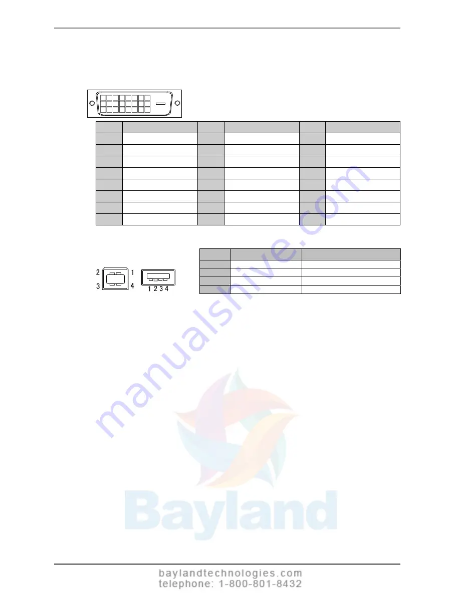
Pin Assignment 

DVI-D Connector

1 2 3 4 5 6 7 8
9

10 11 12 13 14 15 16

19 20 21

17 18

22 23 24

Pin No. 

Signal 

Pin No.

Signal 

Pin No.

Signal 

TMDS Data2- 

TMDS Data1- 

17 

TMDS Data0- 

TMDS Data2+ 

10 

TMDS Data1+ 

18 

TMDS Data0+ 

TMDS Data2/4 Shield 

11 

TMDS Data1/3 Shield

19 

TMDS Data0/5 Shield 

TMDS Data4- 

12 

TMDS Data3- 

20 

TMDS Data5- 

TMDS Data4+ 

13 

TMDS Data3+ 

21 

TMDS Data5+ 

DDC Clock (SCL) 

14 

+5V Power

22 

TMDS Clock shield 

DDC Data (SDA) 

15 

Ground (For +5V) 

23 

TMDS Clock+ 

Analog Vertical Sync

16 

Hot Plug Detect 

24 

TMDS Clock- 

USB Port 

No. 

Signal 

Remarks 

VCC

Cable 

power

- Data

Serial data 

+ Data

Serial data 

Ground

Cable 

Ground

Upstream     Downstream 

Series B    Series A

38

 9. 

SPECIFICATIONS

Summary of Contents for RadiForce R31

Page 1: ...nual for future reference Wichtig Bitte lesen Sie diese Bedienungsanleitung sorgfaltig durch um sich mit dem sicheren und rationellen Betrieb dieses Produkts vertraut zu machen Bewahren Sie das vorlie...

Page 2: ...User s Manual Color LCD Monitor It shall be assured that the final system is in compliance to IEC60601 1 1 requirements...

Page 3: ...stem or transmitted in any form or by any means electronic mechanical or otherwise without the prior written permission of EIZO NANAO CORPORATION EIZO NANAO CORPORATION is under no obligation to hold...

Page 4: ...l Link Cable Connection 16 2 4 10bit Color Signal Input 19 3 MENUS FUNCTIONS 20 3 1 ScreenManager 20 3 2 CAL Switch Function 22 3 3 Other Useful Functions 23 4 ADJUSTMENTS SETTINGS 25 4 1 Color Adjust...

Page 5: ...his section and the caution statements on the unit refer to the figure below Location of the Caution Statements Symbols on the unit Symbol Location This symbol indicates Side Main power switch Press t...

Page 6: ...ice engineer before using it again Place the unit at the strong and stable place A unit placed on an inadequate surface may fall and result in injury or equipment damage If the unit falls disconnect t...

Page 7: ...power cord with care Do not place the cord underneath the unit or other heavy objects Do not pull on or tie the cord If the power cord becomes damaged stop using it Use of a damaged cord may result in...

Page 8: ...ult in injury or equipment damage OK Do not block the ventilation slots on the cabinet Do not place any objects on the ventilation slots Do not install the unit in a closed space Do not use the unit l...

Page 9: ...ain on the LCD panel leave the monitor with a white or black screen The symptom may disappear Do not scratch or press on the panel with any sharp objects such as a pencil or pen as this may result in...

Page 10: ...Ultra slim bezel Image Rotation function see p 23 Dual Link connection support see p 40 10bit color signal input support Signal cable for Dual Link connection supplied NOTE Only designated frequencie...

Page 11: ...p Right 1 5 Power Switch 6 Power Indicator 2 Green The screen is displayed Orange Power saving Flashing orange slowly Power off Main power is on Off Main Power off 1 Right Up Down Left when the monito...

Page 12: ...position It can rotate clockwise ninety degrees By removing the monitor stand the LCD monitor can be used with the optional arm stand see p 31 4 Allows for connection of a security cable This lock sup...

Page 13: ...display support VESA DDC the appropriate resolution and the refresh rate are set just by plugging your display into the computer without any manual settings Single Link Connection Display mode Resolu...

Page 14: ...ion 2 Connect the signal cable to the DVI D input connector on the rear of the monitor and to the video output connector on the PC After connecting secure the cable connectors with the attached screw...

Page 15: ...and and easy rotation between the portrait and landscape positions 5 Connect the other end of the power cord to a power outlet The monitor s power indicator will flash orange slowly WARNING Use the en...

Page 16: ...nment Be sure to take adequate rests A 10 minute rest period each hour is suggested 8 When using the software ScreenManager Pro for Medical connect the USB upstream port on the rear of the monitor to...

Page 17: ...on 2 Connect the signal cable to the DVI D input connector on the rear of the monitor and to the video output connector on the PC After connecting secure the cable connectors with the attached screw i...

Page 18: ...and and easy rotation between the portrait and landscape positions 5 Connect the other end of the power cord to a power outlet The monitor s power indicator will flash orange slowly WARNING Use the en...

Page 19: ...he connection method to Single Link change the Signal Selection setting to Single Link 10bit before turning on the computer 9 When using the software ScreenManager Pro for Medical connect the USB upst...

Page 20: ...ion see p 13 If the image does not display correctly verify the Signal Selection settings Verifying Signal Selection Settings 1 Turn off the monitor s power by touching the power switch 2 Touch the po...

Page 21: ...witch 2 Select the desired setting icon with the directing switches and touch the enter switch 3 Make any required adjustments with the directing switches Exiting the ScreenManager 1 To return to the...

Page 22: ...u Menu Position Adjust the menu position Menu Off Timer Adjust how long to display the menu 2 Menu Settings Translucent Adjust the transparency of the background Power Indicator Disable the green powe...

Page 23: ...e switch Selecting the CAL Switch mode 1 Touch the mode switch while the CAL Switch menu is displayed Making color adjustments in CAL Switch mode 1 Select the desired setting icon with the Up and Down...

Page 24: ...displayed correctly once the computer is restarted Mode Preset When CAL Switch mode is selected the computer can be forced to display only specified modes Use this function when the display modes are...

Page 25: ...ng procedure described above Off Timer The off timer function causes the monitor to turn off automatically after a predetermined amount of time has lapsed This function was created to reduce the after...

Page 26: ...6 colors Reset 1 These settings can also be adjusted on the CAL Switch menu see p 22 2 When calibration is performed in this mode using the calibration kit see Optional p 37 only the brightness and r...

Page 27: ...ation NOTE The Saturation adjustment may cause undisplayable color tone Sets the hue value for flesh tones etc 100 100 Hue NOTE The Hue adjustment may cause undisplayable color tone Sets the gain for...

Page 28: ...horizontal resolution are enlarged at same rates some horizontal or vertical image may disappear Normal Displays the image at the actual Screen resolution Example Displaying 1280 x 1024 resolution at...

Page 29: ...when you are finished using it Disconnecting the monitor from the power supply is recommended to save energy completely Even if the monitor is in power saving mode USB compliant devices draw power wh...

Page 30: ...is not on the peripherals connected to the downstream ports will not operate Even if the monitor is in a power saving mode the devices connected to the monitor s USB ports both the upstream and the d...

Page 31: ...ecting Examples ScreenManager Pro for Medical for Windows For further details about the ScreenManager Pro for Medical for Windows refer to the EIZO LCD Utility Disk Downstream ports Connect the cables...

Page 32: ...ght Total weight of the monitor without stand and attaching equipment such as a cable T V GS approved arm or stand Please connect cables after attaching an arm stand Setup Procedure 1 Hold the center...

Page 33: ...ges shown below remains on the screen for 40 second These messages appear when the video signal is not input correctly even if the monitor functions properly The massage might appear because some PCs...

Page 34: ...led when the screen is displayed at the 2048 1536 resolution The image size is doubled both horizontally and vertically i e 1024 768 enlarged to 2048 1536 to provide a clear focus 10 The ScreenManager...

Page 35: ...r details refer to the PC user s manual 15 The PC freezes The peripherals connected to the USB downstream ports do not operate Check that the USB cable is connected correctly Try connecting the periph...

Page 36: ...onitor before cleaning it Cabinet To remove stains wipe the cabinet with a soft lightly moistened cloth using a mild detergent Do not spray wax or cleaner directly into the cabinet For details refer t...

Page 37: ...TMDS Single Link Dual Link Signal registration 10 Plug Play VESA DDC 2B EDID structure 1 3 With stand 368 mm W x 515 5 597 5 mm H x 209 mm D 14 5 W x 20 3 23 5 H x 8 2 D Dimensions without stand 368 m...

Page 38: ...mal Off Timer Disable Menu Settings Menu Off Timer 45 seconds Language English Optional Arm Stand EIZO LA 131 D EIZO LA 030 W EIZO LA 011 W LCD Monitor Flexible Arm Wall Mount Arm for LCD Monitor Dual...

Page 39: ...ld 11 TMDS Data1 3 Shield 19 TMDS Data0 5 Shield 4 TMDS Data4 12 TMDS Data3 20 TMDS Data5 5 TMDS Data4 13 TMDS Data3 21 TMDS Data5 6 DDC Clock SCL 14 5V Power 22 TMDS Clock shield 7 DDC Data SDA 15 Gr...

Page 40: ...status power saving mode are indispensable for the DVI DMPM as the monitor s power mode Gain Adjustment Adjusts each color parameter for red green and blue The color of the LCD monitor is displayed t...

Page 41: ...er monitors generally give best performance at high temperature settings 5 000 K Slightly reddish white 6 500 K Warm white tone similar to white paper or daylight 9 300 K Slightly bluish white TMDS Tr...

Page 42: ...rence to radio communications However there is no guarantee that interference will not occur in a particular installation If this equipment does cause harmful interference to radio or television recep...

Page 43: ...ormations sur le recyclage pour les clients dans l UE Vous trouverez toutes les informations sur le recyclage dans les sites Web suivants tervinningsinformation f r kunder i EU All information om terv...

Page 44: ...o Hakusan Ishikawa 924 8566 Japan Phone 81 76 277 6792 Fax 81 76 277 6793 EIZO NANAO CORPORATION EIZO NANAO TECHNOLOGIES INC 5710 Warland Drive Cypress CA 90630 U S A Phone 1 562 431 5011 Fax 1 562 43...

Reviews: