background image

18

Chapter4ControllingMonitorQuality

Chapter 4  Controlling Monitor Quality

This product has the built-in Integrated Front Sensor, which allows the user to perform periodic calibration and 
Grayscale Check for the monitor independently.

Attention

•  When a panel protector (RP-903) is installed, the Integrated Front Sensor cannot be used. Do not execute “SelfCalibration” 

or “Grayscale Check” of  “RadiCS SelfQC”. Be sure to set “Meas. Frequency” to “Off”.

•  When a panel protector (RP-913) is installed, the Integrated Front Sensor can be used. After installation, be sure to execute 

correlation using RadiCS/RadiCS LE.

Note

•  To perform advanced quality control that conforms to medical standards, use the optional monitor quality control software 

kit “RadiCS UX1”.

•  Perform correlation using RadiCS/RadiCS LE to adjust the measurement result of the Integrated Front Sensor to the 

measurement result of the UX1 sensor for reference. Periodical correlation enables the measurement accuracy of the 
Integrated Front Sensor equivalent to that of the UX1 sensor. For details, refer to RadiCS/RadiCS LE User’s Manual.

•  “RadiCS” allows you to set the adjustment target for the calibration and judgment value for Grayscale Check, and also the 

schedule for the calibration and Grayscale Check.

•  The supplied “RadiCS LE” software also allows you to set the adjustment target and schedule for the calibration. For details, 

refer to “RadiCS LE User’s Manual” (on the CD-ROM).

4-1.  Executing Calibration

This function allows you to execute SelfCalibration and view the latest result. In addition, when the schedule is set 
using RadiCS/RadiCS LE, the next calibration schedule appears.


Executing SelfCalibration

Attention

•  Do not execute this function when a panel protector (RP-903) is installed.
•  After SelfCalibration is executed, execute Grayscale Check under the actual temperature of the monitor usage 

environment.

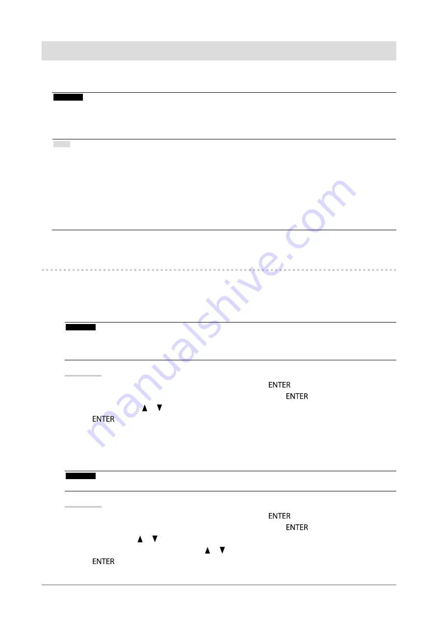
Procedure

1.  Choose “RadiCS SelfQC” from the Adjustment menu, and press 

.

2.  Choose “SelfCalibration” from the “RadiCS SelfQC” menu, and press 

.

3.  Select “Execute” with   or  .
4.  Press 

 to exit.

SelfCalibration is executed.


Viewing SelfCalibration result

Attention

•  The result can be viewed when “QC History” is “On” (see 

“4-4. Setting On/Off for Warning and QC History” (page 20)

).

Procedure

1.  Choose “RadiCS SelfQC” from the Adjustment menu, and press 

.

2.  Choose “SelfCalibration” from the “RadiCS SelfQC” menu, and press 

.

3.  Select “Result” with   or  .
4.  Select “DICOM”, “CAL1” or “CAL2” with   or  .
5.  Press 

 to exit.

The SelfCalibration result (Max. Error Rate, Last Time, and Error Code) appears.

Summary of Contents for RadiForce GX240-CL

Page 1: ...o familiarize yourself with safe and effective usage Please refer to the Setup Manual for basic information ranging from connection of the monitor to a PC to using the monitor The latest User s Manual...

Page 2: ...y form or by any means electronic mechanical or otherwise without the prior written permission of EIZO Corporation EIZO Corporation is under no obligation to hold any submitted material or information...

Page 3: ...luminosity caused by long term use and maintain a stable display When the screen image is changed after displaying the same image for extended periods of time an afterimage may appear Use the screen s...

Page 4: ...he cabinet or panel Note The optional ScreenCleaner is recommended for cleaning the cabinet and panel surface If necessary the stains on the cabinet and panel surface can be removed by moistening part...

Page 5: ...ion 16 3 8 Enabling Disabling DC5V Output 16 3 9 Return To Default Setting 17 To reset the mode adjustments 17 To reset all settings 17 Chapter 4 Controlling Monitor Quality 18 4 1 Executing Calibrati...

Page 6: ...03 is installed the Integrated Front Sensor cannot be used The quality control software RadiCS LE for Windows used to calibrate the monitor and to manage the history is included See 1 2 EIZO LCD Utili...

Page 7: ...g the sensor where it may be exposed to direct sunlight 1 2 EIZO LCD Utility Disk An EIZO LCD Utility Disk CD ROM is supplied with this product The following table shows the disk contents and the over...

Page 8: ...nt Menu 1 Press The Adjustment menu appears Current mode Menu title Setting Menu Item 2 Adjusting Setting 1 Choose a menu to adjust set with and then press 2 Choose an item to adjust set with and then...

Page 9: ...tings 4 4 Setting On Off for Warning and QC History page 20 Power Manager Power Save 5 1 Setting Power Save page 21 Presence Sensor 5 3 Setting the power saving mode when a person leaves the monitor p...

Page 10: ...ersonalize 3 On the Personalization window click Display Settings 4 On the Display Settings dialog box select the Monitor tab and select desired resolution in the Resolution field 5 Click the OK butto...

Page 11: ...tus The mode menu appears Procedure 1 Press The mode menu appears at the bottom left of the screen 2 The mode among the list is highlighted in turn each time is pressed You can switch the mode with or...

Page 12: ...he mode suitable for the monochrome image display area can be set see To select the display mode CAL Switch mode page 11 Setting Range DICOM CAL1 CAL2 Procedure 1 Choose Mode from the Adjustment menu...

Page 13: ...and Base H To set the detection type in the image display area You can set the detection type in the display area Procedure 1 Choose Mode from the Adjustment menu and press 2 Choose Hybrid Assignment...

Page 14: ...orientation A A Portrait SW Select this option when using the Portrait orientation Graphics board utility software is used to rotate the display image 90 degrees A A Portrait HW Select this option whe...

Page 15: ...g Adjustment Menu Display Position You can change the display position of the Adjustment menu Procedure 1 Choose Menu Settings from the Adjustment menu and press 2 Choose Menu Position from Menu Setti...

Page 16: ...disable the DDC communication Normally turn it on during use This is different from the DDC CI communication Procedure 1 Press to turn off the monitor 2 Holding down press for at least two seconds to...

Page 17: ...adjustment value for the currently selected mode to the default settings Procedure 1 Choose Mode from the Adjustment menu and press 2 Choose Mode Reset from Mode and press 3 Select Execute with or 4 P...

Page 18: ...ration and judgment value for Grayscale Check and also the schedule for the calibration and Grayscale Check The supplied RadiCS LE software also allows you to set the adjustment target and schedule fo...

Page 19: ...2 Choose Grayscale Check from the RadiCS SelfQC menu and press 3 Select Result with or 4 Select DICOM Custom CAL1 or CAL2 with or 5 Press to exit Up to the five latest Grayscale Check results Passed F...

Page 20: ...allows you to set On Off for Warning and QC History when the Grayscale Check result is Failed Procedure 1 Choose RadiCS SelfQC from the Adjustment menu and press 2 Choose Settings from the RadiCS Sel...

Page 21: ...s 3 Select Off and either High or Low with or Settings Function High Turns off the backlight The power saving effect is the greatest Low Turns down the backlight to the lowest setting The time until t...

Page 22: ...ion It also cannot be used during the landscape position display Procedure 1 Choose PowerManager from the Adjustment menu and press 2 Choose Presence Sensor from the PowerManager menu and press 3 Sele...

Page 23: ...the problem turn off the monitor and then turn it on again Refer to the user s manual of the device that uses DisplayPort connection for details 2 The message below appears This message appears when...

Page 24: ...ed Check whether the PC is configured to meet the resolution and vertical scan frequency requirements of the monitor see Compatible Resolutions in the Setup Manual 3 Afterimages appear Afterimages are...

Page 25: ...nsor to detect a person 4 The monitor connected with the USB cable is not detected USB devices connected to the monitor does not work Check whether the USB cable is connected correctly see 7 3 Making...

Page 26: ...ower the target brightness 11 The product minimum brightness may be higher than the target brightness Raise the target brightness 34 The sensor may not have worked correctly Turn off the main power wa...

Page 27: ...g another manufacturer s arm or stand use the screws as described below Screws fixing the stand to the monitor When using an arm or stand attach it to meet the following tilt angles of the monitor Up...

Page 28: ...240 CL supplied Signal cable PP300 supplied DVI D connector Digital DVI Digital DisplayPort To PC 2 DisplayPort connector DisplayPort connector To PC 1 To switch among input signals Procedure 1 Choose...

Page 29: ...lays another signal Manual The monitor detects only the PC s signals currently displaying automatically Select an active input signal with Input Procedure 1 Choose Tools from the Adjustment menu and p...

Page 30: ...Devices connected to the USB upstream port and USB downstream port work when the monitor is in power saving mode or when the power button of the monitor is Off Therefore power consumption of the moni...

Page 31: ...from Tools and press The Signal Info appears Example Displaying Monitor Information This function displays the information about the monitor Procedure 1 Choose Tools from the Adjustment menu and press...

Page 32: ...is set to Off Power Off 1 6 W or less when no USB device is connected and DC5V Output is set to Off Main power Off 0 W Input signal connectors DVI D connector DisplayPort connector Standard V1 1a app...

Page 33: ...240 Vac 10 50 60 Hz 0 5 0 45A Power consumption Screen display On 90 W or less Power saving mode 1 6 W or less when only the DVI signal connector is connected no USB device is connected Input Selectio...

Page 34: ...h 12 Mbps full 1 5 Mbps low Supply current Downstream Max 500mA 1 port Main Default Settings CAL Switch Mode The default display mode setting is DICOM Mode Brightness Gamma value DICOM 500 cd m2 DICOM...

Page 35: ...LT 234 9 2 217 8 5 14 5 0 57 18 5 0 73 209 8 2 245 5 9 7 138 5 4 100 3 9 138 5 4 194 7 6 100 3 9 211 8 3 241 9 5 24 5 0 96 327 12 9 24 5 0 96 43 5 1 71 435 17 1 26 5 1 04 Accessories Calibration Kit E...

Page 36: ...DVI I connector for both digital and analog signal inputs DVI DMPM DVI Digital Monitor Power Management DVI DMPM is a digital interface power saving function The Monitor ON operating mode and Active...

Page 37: ...Rite are registered trademarks or trademarks of X Rite Incorporated TouchWare is a trademark of 3M Touch Systems Inc NextWindow is a registered trademark of NextWindow Ltd RealPlayer is a registered...

Page 38: ...itor Install the equipment in a controlled environment where such effects are avoided This is a monitor intended for use in a medical image system It does not support the display of mammography images...

Page 39: ...armful interference to radio communications However there is no guarantee that interference will not occur in a particular installation If this equipment does cause harmful interference to radio or te...

Page 40: ...rmonic emissions IEC EN61000 3 2 Class D Voltage fl uctuations fl icker emissions IEC EN61000 3 3 Complies Guidance and manufacturer s declaration electromagnetic immunity The RadiForce series is inte...

Page 41: ...ransmitters as determined by an electromagnetic site surveya should be less than the compliance level in each frequency rangeb Interference may occur in the vicinity of equipment marked with the follo...

Page 42: ...transmitter m 150kHz to 80MHz d 1 2 P 80MHz to 800MHz d 1 2 P 800MHz to 2 5GHz d 2 3 P 0 01 0 12 0 12 0 23 0 1 0 38 0 38 0 73 1 1 2 1 2 2 3 10 3 8 3 8 7 3 100 12 12 23 For transmitters rated at a maxi...

Page 43: ...d or improper repair by third party other than EIZO and Distributors b Any incompatibility of the Product due to possible technical innovations and or regulations c Any deterioration of the sensor d A...

Page 44: ...des Sensors d Jegliche Verschlechterung der Bildschirmleistung die durch Verschlei teile wie den LCD Panel und oder die Hintergrundbeleuchtung usw hervorgerufen werden z B Ver nderungen von Farbe ode...

Page 45: ...tations possibles c Toute d t rioration du capteur d Toute d t rioration des performances d affichage caus e par la d t rioration des l ments consommables tels que le panneau LCD et ou le r tro claira...

Page 46: ...del sensor d Cualquier deterioro en el rendimiento de la visualizaci n causado por fallos en las piezas consumibles como el panel de cristal l quido y o la luz de fondo etc p ej cambios de color cambi...

Page 47: ...dovuta a possibili innovazioni tecniche e o normative c Qualsiasi deterioramento del sensore d Qualsiasi deterioramento delle prestazioni dello schermo causato dal deterioramento delle parti consumab...

Page 48: ...beroende p f rbrukningsdelar s som LCD panel och eller bakgrundsbelysning etc t ex f r ndringar i f rg f rgj mnhet defekta pixlar inklusive br nda pixlar etc e Alla f rs mringar av Produkten orsakat...

Page 49: ...49 Appendix EIZO Corporation EIZO EIZO EIZO i ii LCD EIZO 5 5 EIZO 7 EIZO EIZO EIZO a EIZO b c d LCD e f g h i LCD EIZO EIZO EIZO EIZO EIZO EIZO...

Page 50: ...r ou une soci t affi li e de votre pays Les adresses des distributeurs sont r pertori es sur le site Web EIZO ci dessous http www eizo com Pour les clients en Suisse veuillez consulter le site Web sui...

Page 51: ...rug Dette produkt forventes ved bortskaffelse at blive indsamlet og genbrugt i overensstemmelse med lovgivningen i dit land for at reducere belastningen af milj et N r du bortskaffer denne produkt ska...

Page 52: ...to za recikliranje v skladu z okoljevarstveno zakonodajo va e dr ave Prosimo da se pri odstranjevanju izdelka obrnete na lokalnega distributerja ali podru nico Kontaktni naslovi so objavljeni na spoda...

Page 53: ...n distribuitor sau un afi liat al rii respective Adresele de contact le g si i pe pagina de web al EIZO http www eizo com Geri D n m Bilgisi Bu r n n at laca zaman lkenizin evre kirlili inin azalt lma...

Page 54: ...54 Appendix China Measures for RoHS Compliance in ChinaRoHS Pb Hg Cd Cr VI PBB PBDE SJ T 11363 2006 SJ T 11363 2006...

Page 55: ...6th Edition January 2014 03V23831F1 U M GX340 Copyright 2011 2014 EIZO Corporation All rights reserved...

Reviews: