background image

16


  User’s Guide

User Functions / Messages

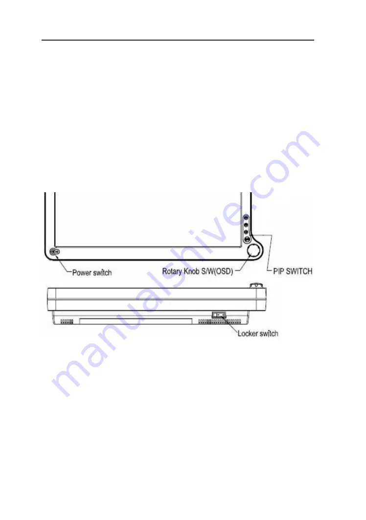
Key Name and Function

Power LED : Lights up to indicate the power is turned ON.

Power Switch : To power ON or OFF the monitor.

Rotary switch : With the OSD menu activated, increases the value of the selected 

(Ture Right)      parameter or moves rightward in OSD menu.

Rotary switch : With the OSD menu activated, increases the value of the selected 

(Ture Left)         parameter or moves leftward in OSD menu.

PIP Switch : To enable or disable Picture In Picture function.

PBP Switch : To enable or disable Picture By Picture function.

POP Switch : To enable or disable Picture On Picture function.

Adjust Switch : To activate or deactivate image adjustment in sub screen of PIP, 


           PBP, POP mode.

Locker Switch : To turn ON or OFF the system.

How to access the menu

1. Push the “Knob” button to activate the OSD menu.

2. Able to turn left or right the button to select those icons. The icon will be 

    highlighted when is selected.

3. Push the “knob” button to go into the another OSD menu.

4. Turn left or right “Knob” button to increase or decrease the number of selected 

    function.

5. In order to exit from the OSD menu in a different layer, then choose the “Exit 

    option”. In case of long pushing and holding the button around two or three 

    seconds, then it will completely out from the menu regardless wherever you are.

6. Turn the “Knob” button in a fast way to the left or right, while the menu is not 

    activated, then input signal menu will turns up with “V” mark which is chosen 

    current available input signal. You can switch to another input signal source by 

    turning the knob slowly then select the target source by pushing the knob.

Summary of Contents for RadiForce EX210

Page 1: ...TROL LCD COLOR MEDICAL MONITOR Operation Manual For future reference record the serial number of your display monitor in the space below Serial Number The serial number is located on the back of the m...

Page 2: ......

Page 3: ...inform the users of pos sible causes that could inflict the injury death or property damage to the patients CAUTION The title CAUTION is used to inform the users of pos sible causes that could inflict...

Page 4: ...ent Function Preset Modes Video Signals PIP POP PBP function DDC Installation Connecting the Power Cord User Function Messages OSD Section Troubleshooting Specification of EX210 EX240W Classification...

Page 5: ...e monitor in future EX210 EX240W LCD Monitor and two video cables 1 HD15 VGA cable 1 DVI D cable AC Power cord AC Adapter Composite Video BNC Jack Cable and Super Video Cable User Manual and 4pcs VESA...

Page 6: ...ENT AND OR DAMAGE TO THIS DEVICE THE USER MUST Warranty is void if any of these warnings are disregarded EIZO Nanao Corporation accepts full responsibility for the effects on safety reliability and pe...

Page 7: ...s for medical devices in IEC 601 1 2 2003 These limits are designed to provide reasonable protection against harm ful interference in a typical medical installation This equipment generates uses and c...

Page 8: ...pment with strong magnets i e a large loudspeaker 16 Do not expose the monitor to moisture or excessive dust 17 Equipment with SIP SOP connectors should either comply with IEC 60601 1 and or IEC 60601...

Page 9: ...tives and to harmonized standards published in the official journal of the European Communities Authorized Representative in Europe Indicates protective earth ground For indoor use only Medical Equipm...

Page 10: ...l convection it has no fan For optimum performance do not block the cooling vents While unpacking the monitor inspect it and other package contents for shipping damage that could cause a fire or shock...

Page 11: ...ain from giving the shock or scratch to the screen as screen is fragile CLEANING YOUR MONITOR No specific liquid or chemical necessary when cleaning this LCD monitor However we suggest to clean the mo...

Page 12: ...The monitor goes into power off mode when the vertical and horizontal sync signals are off for about 10 seconds In this mode the screen goes off and the power LED blinks for 1 seconds On and 1 second...

Page 13: ...5Hz 46 875 75 000 49 500 800 x 600 85Hz 1 53 674 85 061 56 250 1024 x 768 60Hz 48 363 60 004 65 000 1024 x 768 70Hz 56 476 70 069 75 000 1024 x 768 75Hz 60 023 75 029 78 750 1024 x 768 85Hz 1 68 677 8...

Page 14: ...76 50p O O O O 720 50p O O O O O O 720 59 94p O O O O O O 720 60p O O O O O O 1080 23 98psf O O O O O 1080 24psf O O O O O 1080 23 98p O O O O O 1080 24p O O O O O 1080 25p O O O O O O 1080 29 97p O O...

Page 15: ...tions are available to you Main PIP VGA DVI SDI1 SDI2 C Video S Video Component RGBs SOG VGA O O O O O O O DVI O O O O O O O O SDI1 O O O O O O O SDI2 O O O O O O O C Video O O O O O O O S Video O O O...

Page 16: ...nstall the monitor to your host system please follow the steps as given below Steps 1 Use the supplied video cable DVI VGA S Video C Video then connect to the host system accordingly 2 Connect the DC...

Page 17: ...e safety approvals for the country in which the equipment will be installed and marked HAR For 120 volt Applications use only UL Listed deachable power cord with NEMA configuration 5 15P type parallel...

Page 18: ...witch To turn ON or OFF the system How to access the menu 1 Push the Knob button to activate the OSD menu 2 Able to turn left or right the button to select those icons The icon will be highlighted whe...

Page 19: ...Sharpness H Sharpness V Setting Adjust Scale Mode Color Space Mirror Freeze Frame Zoom Pan PIP POP PBP EIZOced Adjust OSD Position Control Screen Control DPMS Auto Source Select Smart Select Restore F...

Page 20: ...sual Brightness Adjust the brightness of panel Range 0 100 Contrast Adjust the contrast of video Range 0 100 Phase Adjust the phase of video Range 0 100 available for C and S video Chroma Adjust the c...

Page 21: ...color space between RGB and YPbPr available for Component and RGBS Mirror Off On mirror image Freeze Frame Off On freeze frame Zoom Pan Enable zoom in and pan function PIP Enable PIP Picture In Pictur...

Page 22: ...n position Top L Top R Bottom L Bottom R Size PIP sub screen size Small Medium Large Blending PIP sub screen blending Range 0 100 Swap PIP sub screen swap Exit Exit the menu Mode PBP Mode ON Off Sourc...

Page 23: ...omponent VGA DVI SOG Position POP sub screen position Top L Top R Bottom L Bottom R Size POP sub screen size Small Medium Large Full Blending POP sub screen blending Range 0 100 Swap POP sub screen sw...

Page 24: ...Control and adjust H and V position Freqency Phase Noise Reduction Motion Offset DPMS Change the DPMS Auto Source Adjust Auto Source Select between on and off Select Smart Select Enable Disable smart...

Page 25: ...German Exit Exit the menu H position Adjust screen H position Range 0 100 available for VGA V position Adjust screen V position Range 0 100 available for VGA Frequency Adjust frequency Range 0 100 ava...

Page 26: ...ction Information Custom Entry Change the user or monitor s name SN Display the serial number Run Time Display the total run time Input Format Display the current input resolution and vertical frequen...

Page 27: ...power to computer system is ON Abnormal Picture Unstable Picture Check if the specification of graphics adapter and monitor is in compliance which may be causing the input signal frequency mismatch D...

Page 28: ...les Brightness 750 cd m2 Typ 400 cd m2 Typ Contrast Ratio 1100 1 Typ 1000 1 Typ Signal Input Connector Video DVI HD15 SD HD SDI 1 and 2 Compo nent Y G Pb B Pr R H CS VS C Video and S Video DVI HD15 SD...

Page 29: ...rd UL60601 1 UL cUL Mark Because many medical offices are located in residential areas this monitor in ad dition to the medical requirements has also been tested and found to comply with the limits fo...

Page 30: ...up 1 The Model EX210 EX240W uses RF energy only for its internal function Therefore its RF emissions are very low and are not likely to cause any interference in nearby electronic equipment RF emissio...

Page 31: ...cables than the recommended separation distance calculated from the equation applicable to the frequency of the transmitter Recommended Separation Distance 0 15 MHz to 80 MHz 80 MHz to 800 MHz 800 MHz...

Page 32: ...itter Separation distance m according to frequency of transmitter 150kHz to 80MHz d 1 17 p 80MHz to 800MHz d 1 17 p 800MHz to 2 5GHz d 2 33 p 0 01 0 12 0 12 0 23 0 1 0 37 0 37 0 74 1 1 17 1 17 2 33 10...

Page 33: ...Dimension Drawing mm of EX210 EX210 EX240W 31 ENGLISH...

Page 34: ...32 User s Guide Dimension Drawing mm of EX240W...

Page 35: ...tect 26 Analog Green 7 DDC Data 17 T M D S Data0 27 Analog Blue 8 Analog V Sync 18 T M D S Data0 28 Analog H Sync 9 T M D S Data1 19 T M D S Data0 Shield 29 GND for analog signal 10 T M D S Data1 20 N...

Page 36: ...sallee 84 D 76187 Karlsruhe Germany Tel 49 721 20321 0 Fax 49 721 20321 474 Web Page http www eizo eu 924 8566 153 076 275 4121 Fax 076 275 4125 Web http www radiforce com Exclusive Distributor EIZO N...

Reviews: